Description
Triconex 2401 Technical Specifications:
- Output Channels: 8 independent digital output channels.
- Output Voltage: 24 VDC nominal.
- Output Current: 1A per channel maximum.
- Protection: Integrated short-circuit protection and overload protection.
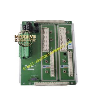
- Form Factor: Modular base design compatible with Triconex chassis.
Functional Features:
- High-Drive Capability: Capable of directly driving industrial relays and solenoid valves.
- Fault Tolerance: Continuous monitoring of output circuit integrity with automatic fault detection.
- Hot-Swappable: Supports online replacement of modules without shutting down the safety system.
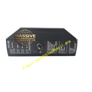
- Visual Indication: Front-panel LEDs provide immediate status feedback for each output channel.
Application Scenarios:
- Emergency Shutdown (ESD) systems in oil and gas facilities.
- Burner Management Systems (BMS) in power generation.
- Process interlocks and safety permissives in chemical plants.
- Control of pneumatic and hydraulic valve actuators.
Performance Parameters:
- Response Time: Fast output switching for rapid safety action.
- Reliability: Triple Modular Redundancy (TMR) architecture support for SIL 3 applications.
- Isolation: Galvanic isolation between field outputs and internal logic.
Material Composition & Structural Characteristics:
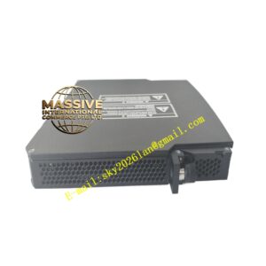
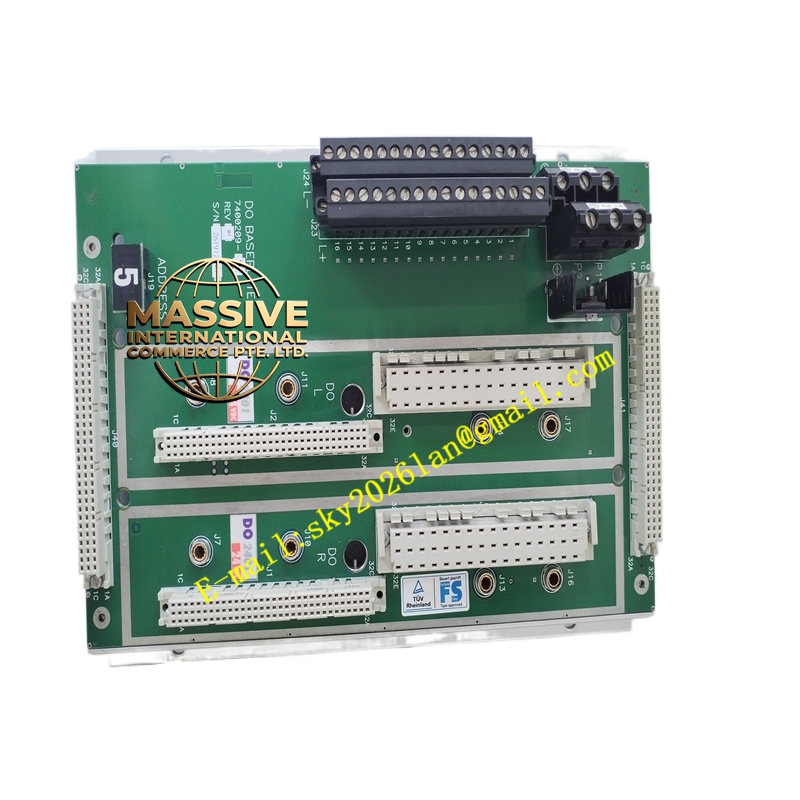
- Dimensions: 176mm x 88mm x 25mm.
- Weight: Approximately 300g.
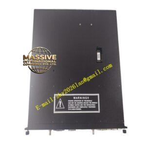
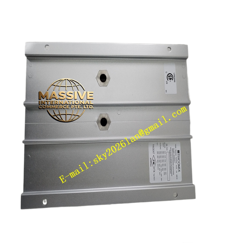
- Base Material: High-temperature thermoplastic housing with metal reinforcement.
- Terminals: Front-access screw terminals for field wiring, with clear channel labeling.
Working Principle: The 2401 base module receives digital control signals from the Triconex processor via the TriBus backplane. It conditions these signals and provides the necessary 24VDC power and current amplification to energize the connected field devices. Continuous diagnostic circuits monitor the output transistors and field wiring for open circuits, short circuits, and overcurrent conditions.
Installation Requirements:
- Wiring: Use appropriately sized conductors for the 1A output current rating.
- Fusing: Install external fuses if required by the specific application safety analysis.
- Mounting: Securely mount on the Triconex baseplate and engage the locking mechanism.
- Testing: Perform loop checks and functional tests after installation.
Usage Precautions:
- Load Matching: Verify that connected loads do not exceed the 1A/24VDC rating.
- Inductive Loads: Use flyback diodes or snubber circuits across inductive loads to protect output transistors.
- Short Circuit: Investigate and clear any short circuit conditions before resetting the output.
- ESD Protection: Handle the module with ESD precautions to prevent damage to sensitive electronics.