Description
Triconex 9565-810F Technical Specifications:
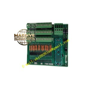
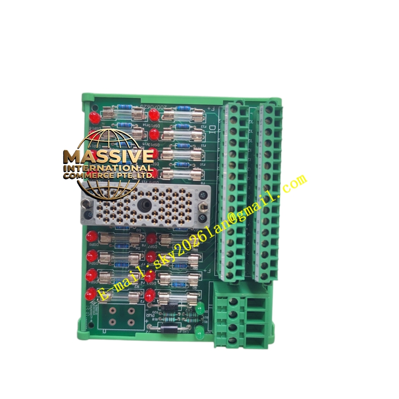
- Output Interface: Screw terminals for field load connections.
- Module Compatibility: Designed for Tricon digital output modules (e.g., 3601E, 3603E).
- Load Voltage: Supports 115VAC, 120VDC, or 24VDC loads.
- Current Capacity: Rated for standard industrial solenoid and relay coil currents.
Functional Features:
- Flyback Protection: Integrated suppression diodes or RC snubbers for inductive loads.
- Fused Outputs: Individual or grouped fusing to protect against short circuits.
- Status Indication: Optional LED indicators for local output status verification.
- Safe Disconnect: Designed to allow safe isolation of field loads for maintenance.
Application Scenarios:
- Actuating emergency shutdown valves (ESDV).
- Controlling motor starters and contactors.
- Driving alarm horns, beacons, and annunciator panels.
- Safety system permissive outputs.
Performance Parameters:
- Switching Capacity: Rated for high inrush currents typical of solenoid valves.
- Contact Resistance: Low resistance path to minimize voltage drop.
- Thermal Rating: Designed to dissipate heat generated by continuous output currents.
Material Composition & Structural Characteristics:
- Housing: High-impact, flame-retardant plastic enclosure.
- Contacts: Silver-alloy plated terminals for low resistance and corrosion resistance.
- Protection Components: Surface-mount diodes, resistors, and fuses.
- Backplane Connector: High-reliability edge connector.
Working Principle: The digital output module sends control signals through the backplane to the 9565-810F terminal board. The terminal board routes these signals to the appropriate field terminals. When the module energizes an output, current flows from the field power supply, through the module’s switching element, through the terminal board, and into the field load.
Installation Requirements:
- Load Wiring: Connect field loads using appropriately sized wire for the current rating.
- Polarity: Observe correct polarity for DC outputs and diode protection.
- Snubber Installation: Install external snubbers if required for highly inductive loads.
- Module Mating: Ensure the terminal board is fully seated and locked to the I/O module.
Usage Precautions:
- Inductive Loads: Always verify flyback protection is functional to prevent module damage.
- Short Circuit Protection: Never bypass output fuses; replace with identical ratings only.
- Safety: Lockout/tagout field power before working on terminal connections.
- Heat Dissipation: Ensure adequate airflow around high-current output terminals.