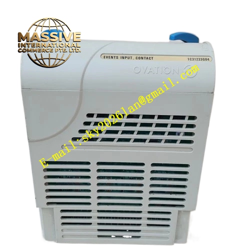
Description
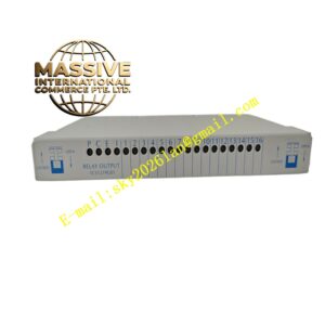
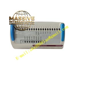
Emerson A6110
Technical Specifications
- Multi-channel data acquisition and logic processing
- Operating temperature: 0°C to 60°C
- Storage temperature: -40°C to 85°C
- Ambient humidity: 5% to 95% non-condensing
- Built-in flash memory for parameter storage
- Communication port for host system connection
Functional Features Collects real-time measurement data and fault information from all modules in rack. Executes alarm and trip logic judgment according to preset thresholds. Stores configuration parameters and historical event logs. Supports data upload to upper monitoring host. Continuous self-diagnosis for internal hardware and rack bus status. Front panel LED indicators display running state, alarm and system fault information.
Application Scenarios Installed in machinery protection racks for steam turbines, centrifugal compressors and large rotating equipment in power plants and petrochemical plants. Acts as core processing unit of machinery protection system.
Performance Parameters
- Fast logic calculation speed for protection judgment
- Stable data storage of configuration parameters
- High diagnostic coverage of rack hardware faults
- Reliable long-term continuous operation
Material Composition High-performance industrial PCB substrate. Main processing chip, memory chips and communication chips. Gold-plated backplane connector pins. Flame-retardant plastic front panel with LED windows. Metal shielding layer reduces electromagnetic interference.
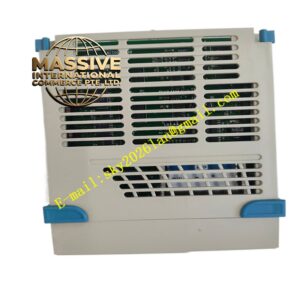
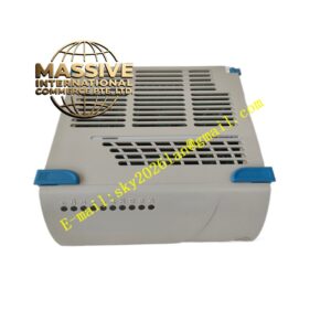
Structural Characteristics Standard rack plug-in card form factor. Front panel equipped with LED indicators. Mechanical locking buckle prevents loosening under vibration. Internal circuit layout separates high-speed logic circuit and analog signal circuit.
Working Principle The module receives measurement data and diagnostic messages from vibration, speed and displacement monitoring modules via rack backplane bus. Internal processor compares real-time measured values with preset alarm and trip thresholds and executes protection logic. All event information is stored in local memory and uploaded to upper monitoring system. Onboard self-test circuit checks hardware and bus status continuously and reports system faults.
Installation Requirements Insert the module into dedicated main processor slot of machinery protection rack and lock buckle. Ensure reliable rack grounding. Keep ventilation channels unobstructed. Route communication cables separately from high-voltage power cables.
Use Precautions Complete parameter configuration and full system test after installation. Do not modify threshold parameters arbitrarily during equipment running. Backup configuration parameters regularly. Replace module when permanent hardware fault appears in self-diagnosis report.