



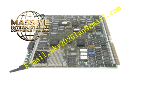
Description
Honeywell 51401551-400
Technical Specifications
- Backplane Interface: TDC3000 proprietary control backplane bus
- I/O Bus Interface: TDC3000 local I/O parallel bus
- Power Supply: 5VDC and 12VDC from rack backplane
- Operating Ambient Temperature: 0°C to +60°C
- Storage Temperature: -40°C to +85°C
- Relative Humidity: 5% to 90% RH non-condensing
- Mounting Type: Plug-in slot installation on TDC3000 I/O rack
- Certification: UL, CE, RoHS
- Maximum Supported I/O Modules: 16 paddle cards per rack
Functional Features It executes cyclic polling to all I/O modules on local I/O bus. It collects analog measurement value and digital status signal from each I/O card. It receives control output command from main processor and forwards command to target I/O channel. It detects I/O module offline, bus short circuit and communication timeout fault. It carries built-in bus overcurrent protection and surge suppression circuit. It carries front panel LED indicators for power, run status, bus active and fault. It supports hot swap of compatible I/O modules. It stores I/O point mapping and polling parameter in non-volatile memory. It uploads I/O diagnostic information to TDC3000 operator station.
Application Scenarios TDC3000 I/O expansion rack master control board Petrochemical plant field signal collection rack Refinery temperature, pressure and discrete signal control rack Power plant auxiliary system TDC3000 I/O cabinet Natural gas processing station remote I/O control node
Performance Parameters
- I/O Bus Polling Cycle: Configurable from 10ms to 1000ms
- Mean Time Between Failures: 770000 hours
- Insulation Resistance: Greater than 1000 MΩ
- ESD Immunity: 8kV contact discharge
- Bus Communication Accuracy: ±0.05% timing error
Material Composition FR4 flame retardant conformal coated multilayer PCB 32-bit microcontroller and bus arbitration logic chip Bus transceiver and signal isolation components Current monitoring and overcurrent protection circuit Flash memory and RAM chips TVS surge suppression components Gold plated edge connector for backplane Metal front panel with extraction handle and LED indicators
Structural Features Standard paddle card form factor. Front panel integrates grouped LED indicators and extraction handle. Rear gold plated edge connector mates with rack backplane power and control bus. Internal PCB layout separates high-speed I/O bus trace and control logic trace. Independent current limiting circuit protects each I/O bus segment. Anti-key notch prevents reverse insertion into rack slot. Locking clip secures module firmly after installation. Conformal coating covers PCB surface to resist corrosive industrial atmosphere.
Working Principle After power on, the module loads I/O configuration and initializes local I/O bus. It sends polling command to each I/O module in preset sequence. It receives sampled data from I/O modules, packages data and transmits to main processor via backplane bus. It receives output command from main processor and sends command to designated I/O card. When bus short circuit or module offline is detected, protection circuit limits bus output and fault flag is generated. Fault information is uploaded to operator station for alarm display.
Installation Requirements Wear anti-static wrist strap before inserting module into dedicated I/O control slot of rack. Lock extraction handle after full seating. Complete backplane bus connection with main processor rack. Configure I/O polling cycle and point mapping in engineering workstation. Power on rack and verify run LED steady on. Insert I/O paddle cards one by one and confirm module recognition. Separate I/O bus cable from high voltage power cable in wiring duct.
Usage Notes Do not insert incompatible non- I/O modules into the rack. Do not exceed the maximum supported I/O quantity limit. Check bus load current before adding new I/O subrack. Recalibrate polling timing parameter after batch replacement of I/O cards. Replace module when all I/O modules fail to communicate simultaneously.







