Description
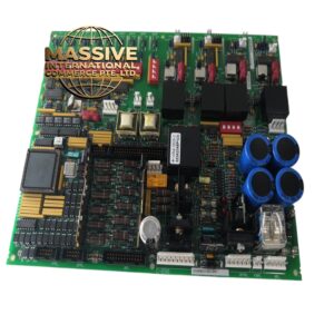
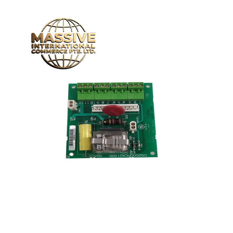
GE DS200CPCAG1ABB
Technical Specifications
-
Manufacturer: General Electric (GE)
-
Series: Mark V Speedtronic
-
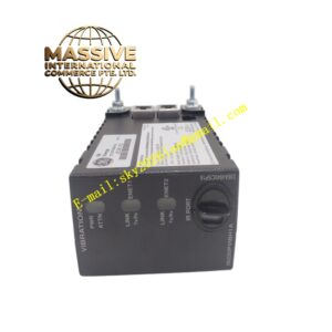
Function: Contactor Pilot Card / Turbine Control Module
-
Connectors: One 12-pin connector and two 2-pin connectors
-
Terminal Blocks: Four terminal blocks supporting up to 12 signal wires
-
Power Relay: Integrated 24VDC 15A socket power relay
- Voltage Output Ranges:
-
Bipolar: Selectable 2.5V, 5V, or 10V
-
Unipolar: 0–2.5V, 0–5V, or 0–10V
-
-
Current Output Ranges: 4–20mA, 0–20mA, or 5–25mA
-
Resolution: High-resolution analog output for precise turbine parameter control
-
Construction: High-strength materials with excellent mechanical strength and corrosion resistance
Functional Features
-
Precise dimensional design ensures perfect compatibility with GE contactors
-
Provides guidance and support for contactor installation positioning
-
High-resolution voltage and current output capability for accurate turbine control
-
Multiple connector configurations for complex signal routing
-
Rugged construction withstands harsh industrial environments
Application Scenarios
-
Turbine Control Module: Receives and processes sensor signals, outputs control signals to regulate turbine speed and power parameters, ensuring stable operation and high-efficiency performance
-
Contactor Guidance Board: Ensures correct contactor positioning in electrical cabinets while providing necessary electrical connections for complex control requirements
Structural Characteristics
-
Precision-machined mounting features for accurate contactor alignment
-
Multiple connector types for flexible wiring configurations
-
Heavy-duty terminal blocks with secure wire retention
-
Corrosion-resistant surface treatment for long-term reliability
Installation Requirements
-
Install in designated position within Mark V control cabinet
-
Ensure proper alignment with corresponding contactor assemblies
-
Connect all signal wires according to wiring diagram specifications
-
Verify relay coil voltage compatibility (24VDC)
Operational Precautions
-
Handle with care to prevent damage to precision alignment features
-
Ensure all connectors are fully seated and locked
-
Verify output voltage/current ranges match application requirements
-
Inspect terminal connections periodically for loosening due to vibration