Description
GE 8811-IO-DC
Technical Specifications:
- Input Channels: 8 binary inputs (dry contact, voltage-free)
- Output Channels: 4 relay outputs (form C changeover contacts)
- Input Voltage Range: 12V DC to 250V DC (wide range compatible)
- Input Contact Rating: 5A at 250V DC (resistive load)
- Output Contact Rating: 5A at 250V DC / 250V AC (resistive load)
- Output Contact Type: 4 Form C (1 common, 1 NO, 1 NC per output)
- Isolation Voltage: 2500V AC between inputs and outputs (optical isolation)
- Power Supply: 24V DC to 250V DC (same as relay supply)
- Power Consumption: Less than 3W typical
- Communication: RS-485, Modbus RTU protocol
- Baud Rate: 9600, 19200, 38400, 115200 bps selectable
- Module Address: 1 to 32 (configurable via DIP switches or software)
- Operating Temperature: -20°C to +70°C
- Storage Temperature: -40°C to +85°C
- Humidity: 5% to 95% non-condensing
- Dimensions: Approximately 110mm x 90mm x 65mm (H x W x D)
- Weight: Approximately 0.4kg
- Mounting: DIN rail (35mm) or panel mount with screws
- Standards: IEC 61850 (communication), IEC 60255 (protection), UL 508, CE marked
Functional Features:
- Each of the 8 binary inputs is fully optically isolated from the relay and from each other, preventing ground loops and noise coupling
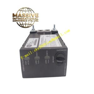
- Each input has a green LED indicator that illuminates when the input is active (closed contact)
- Each of the 4 relay outputs has a red LED indicator showing output status
- Supports both normally open (NO) and normally closed (NC) contact configurations per output via software
- Inputs can be configured for edge detection (rising/falling) for event counting applications
- Outputs can be configured for latching or non-latching operation
- Front panel test button allows manual activation of all outputs for commissioning
- DIP switches on the module allow quick address setting without software
- Hot-swappable design allows module replacement without de-energizing the relay
Application Scenarios:
- Substation control panels for breaker status monitoring (open/close indication)
- Motor control centers (MCC) for interlocking and sequencing
- Remote terminal units (RTU) in power distribution networks
- Pump station automation for level switches and valve position feedback
- HVAC system control for damper position and fan status
- Fire alarm interface panels
- Oil and gas SCADA remote I/O stations
Performance Parameters:
- Input Response Time: Less than 10ms (typical)
- Output Operating Time: Less than 15ms (typical)
- Isolation Resistance: Greater than 100MΩ at 500V DC
- Dielectric Strength: 2500V AC for 1 minute between input and output
- Mechanical Life: 10 million operations (relay outputs)
- Electrical Life: 500,000 operations at rated load (relay outputs)
- MTBF: Greater than 200,000 hours at 25°C
Material Composition:
- Housing: Flame-retardant ABS plastic (UL94 V-0)
- Terminal Blocks: Copper alloy with nickel plating
- PCB: FR-4 with conformal coating for moisture protection
- Optocouplers: Industrial grade with CTR greater than 100%
- LEDs: High-brightness, 100,000 hour life
Structure Features:
- Compact 90mm wide module fits in standard relay panels
- Color-coded terminal blocks: green for inputs, red for outputs, blue for power
- Plug-in connector for relay bus communication (no wiring required between module and relay)
- DIN rail clips included for secure mounting
- Clear labeling area on front panel for circuit identification
Working Principle: The module communicates with the host relay via an internal bus connector. The host relay sends commands to set output states and reads input states periodically (typically every 10ms). Each input is monitored by an optocoupler that detects the presence of DC voltage across the dry contact. When the contact closes, the optocoupler conducts and the input state is reported to the relay. Outputs are driven by relay coils controlled by the host relay via transistor drivers. Installation Requirements:
- Connect to the host relay using the included bus connector (no external wiring for communication)
- Wire binary inputs using shielded twisted pair cables
- Wire relay outputs using 1.5mm² to 2.5mm² copper conductors
- Connect the module power supply to the same DC bus as the host relay
- Set the DIP switch address to match the relay configuration
Usage Notes:
- Do not mix AC and DC inputs on the same module
- Keep input wiring away from high-current power cables to avoid EMI
- Verify all input polarities before energizing (some inputs are polarity sensitive)
- Test each output using the front panel test button before connecting to field devices