
Description
GE DS200NATOG2A
Technical Specifications
-
Manufacturer: General Electric (GE)
-
Series: Mark V Speedtronic
-
Function: Voltage Feedback Scaling Board
-
Physical Dimensions: 8.26 × 4.18 × 4.62 cm / 8.8″ × 3.6″ × 4.7″
-
Weight: 0.5 kg (without packaging)
-
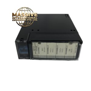
Interface Type: 20-pin ribbon connector supporting 5-way output series connection
-
Input Voltage Ranges: AC/DC input supporting multiple voltage levels:
-
VLG: 1270.17V
-
VLL: 2200V
-
Additional ranges: 6900V, 4200V, 3300V, 1200V
-
-
Output Voltage Range: 0V to 10V
-
Accuracy: ±0.5% (some sources indicate ±1%)
-
Working Voltage: AC/DC input, multi-voltage grade support
-
Operating Temperature: 20°C to +70°C (industrial standard) / -40°C to +70°C (extended)
-
Protection Rating: IP65
-
Installation: Requires use with LS2100 series VME backplane (such as DS200VMEBG1A) and gate distribution status board (such as DS200GDSAG1A)
-
Certifications: CSA, EC, UL certified, compliant with industrial electromagnetic compatibility requirements
Functional Features
-
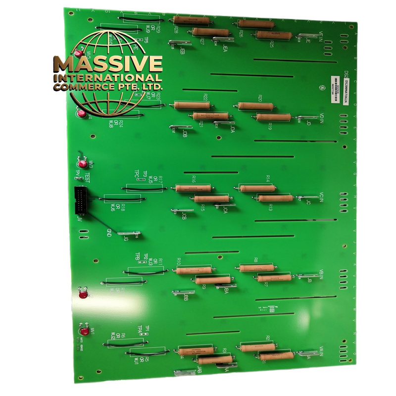
High-Precision Voltage Conditioning: Employs precision resistor networks and adjustable jumper designs to accurately attenuate AC and DC input voltages, ensuring output signal error less than ±1%. When input voltage is 2200V, VLG output stabilizes at 1.905V, meeting stringent control system signal precision requirements
-
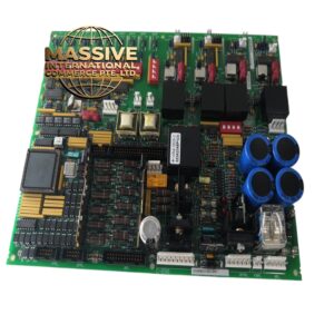
Redundant Protection Mechanism: Built-in MOV (Metal Oxide Varistor) protection circuit rapidly suppresses overvoltage when output lines are interrupted, preventing equipment damage. This design is particularly suitable for high-voltage environments such as instantaneous voltage fluctuations during gas turbine starting phases
-
Multiple Input Configurations: Equipped with multiple VLG and VLL inputs for flexible application requirements
-
Rugged Construction: Suitable for harsh industrial environments with comprehensive protection
Application Scenarios
-
Gas Turbine Control Systems: Provides precise voltage feedback from SCR power bridges for turbine speed and power control
-
Steam Turbine Excitation Systems: Monitors excitation bridge voltage for stable generator output
-
Industrial Motor Drives: Provides voltage feedback for large DC motor drive systems
-
Power Generation Facilities: Critical component in voltage closed-loop control systems
-
High-Voltage Industrial Processes: Applications requiring precise high-voltage measurement and scaling
Structural Characteristics
-
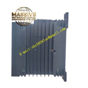
Compact rectangular PCB design optimized for high-voltage applications
-
Precision resistor networks with low temperature coefficient
-
MOV protection devices strategically placed for surge suppression
-
20-pin ribbon connector for reliable signal transmission
-
Conformal coating for environmental protection in harsh conditions
Working Principle The board receives high-voltage AC or DC signals from SCR power bridges through precision voltage divider resistor networks. These resistor networks proportionally attenuate the high input voltages to safe, measurable levels (0–10V) suitable for Mark V control system analog inputs. The attenuation ratio is precisely calibrated to maintain accuracy across the full operating range. MOV protection devices clamp transient overvoltages to protect downstream circuitry.
Installation Requirements
-
Must be installed in conjunction with LS2100 series VME backplane (DS200VMEBG1A)
-
Requires gate distribution status board (DS200GDSAG1A) for proper operation
-
Install in Mark V control cabinet high-voltage feedback section
-
Ensure proper grounding and shielding for high-voltage inputs
-
Verify jumper settings match application voltage ranges
Operational Precautions
-
High-voltage inputs present electrical shock hazard—ensure all power sources are de-energized before installation
-
Verify proper scaling factor configuration for application voltage levels
-
Inspect MOV protection devices periodically for degradation
-
Monitor output signal accuracy through system diagnostic software
-
Ensure proper ventilation to prevent overheating of precision components