Description
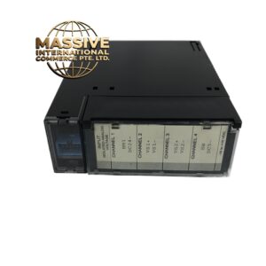
GE D20C PANEL
Technical Specifications:
- Relay Type: D20C-1 (non-directional OC), D20C-2 (directional OC), D20C-3 (differential), D20C-4 (distance)
- Current Rating: Up to 500A CT primary (with 5A secondary)
- Voltage Rating: Up to 690V AC (for motor protection), up to 69kV (with PTs for transformer protection)
- Number of Relays: Up to 6 relays in standard configuration
- Enclosure Rating: NEMA 1 (indoor) or NEMA 4X (outdoor, stainless steel)
- Door Type: Hinged with neoprene gasket (NEMA 4X option has continuous gasket)
- Wiring Entry: Rear entry with PG21 cable glands (up to 8 entries)
- Front Terminals: 12-position terminal block for trip/alarm output wiring
- Dimensions: 800mm x 600mm x 250mm (H x W x D, standard)
- Weight: Approximately 35kg to 50kg (depending on relay configuration)
- Standards: IEC 60529 (IP rating), IEC 60255 (protection), NEMA 250, UL 508A
Functional Features:
- Pre-wired at the factory with all CT, PT, trip, and alarm connections
- Front-panel LED indicators show relay status for each phase (R, Y, B)
- Push-button test and reset on the door for each relay
- Wiring diagram printed on the inside of the door for field reference
- Space for up to 6 D20C relays with individual status LEDs
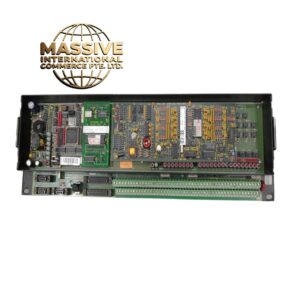
- Rear terminal blocks for CTs, PTs, trip coils, and binary I/O
- Ground bus bar with multiple bonding points
- Surge protection compatible (DIN rail modules can be added)
Application Scenarios:
- Mining equipment protection (conveyor belts, crushers, mills)
- Water and wastewater treatment plant motor protection
- Oil and gas platform feeder and motor protection
- Marine shore power and propulsion motor protection
- Cement plant kiln and mill motor protection
- Steel plant rolling mill motor protection
Performance Parameters:
- Relay Operating Time: Less than 35ms for internal faults (D20C-3 differential)
- Communication Response: Less than 100ms via RS-485 to SCADA
- Dielectric Strength: 2000V AC for 1 minute (panel to ground)
- Insulation Resistance: Greater than 100MΩ at 500V DC
- Vibration Resistance: IEC 60068-2-6 compliant (5g, 10-150Hz)
- Shock Resistance: IEC 60068-2-27 compliant (15g, 11ms)
Material Composition:
- Enclosure: 1.5mm cold-rolled steel with powder-coat finish (NEMA 1) or 316L stainless steel (NEMA 4X)
- Door Gasket: EPDM rubber (NEMA 4X) or neoprene (NEMA 1)
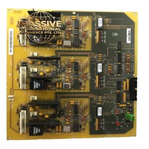
- Internal Wiring: 1.5mm² to 4mm² copper conductors, color-coded
- Terminal Blocks: Copper alloy with tin plating, UL listed
- Relay Mounting Plates: 2mm aluminum with anodized finish
Structure Features:
- Hinged door opens 120 degrees for full access to relays
- Internal DIN rail for relay mounting and I/O modules
- Rear cable entry with removable knockouts
- Front-panel nameplate shows panel identification, relay types, and CT/PT ratios
- Key-operated door lock (NEMA 4X option)
- Lifting lugs on top for crane installation
Working Principle: Each D20C relay receives CT and PT signals via the rear terminal blocks. The relay processes the measurements and applies the programmed protection curves. When a fault is detected, the relay closes its trip output contact, which sends a signal through the front terminal block to the circuit breaker trip coil. The SCADA system receives real-time data via the RS-485 bus connected to the relay. Installation Requirements:
- Mount panel on a flat, level surface or wall with adequate clearance (300mm front, 200mm rear)
- Connect CTs and PTs to the rear terminal blocks using shielded cables
- Connect trip outputs to the circuit breaker trip coils
- Connect binary I/O to the control system via the rear terminal block
- Ground the panel chassis to the site ground grid using 16mm² green/yellow cable
- Perform factory acceptance test (FAT) before shipping
Usage Notes:
- Verify all CT and PT ratios match the relay settings before energizing
- Perform relay commissioning test using the front-panel test button
- Backup all relay settings to non-volatile memory
- Schedule annual maintenance including contact cleaning and insulation testing