Description
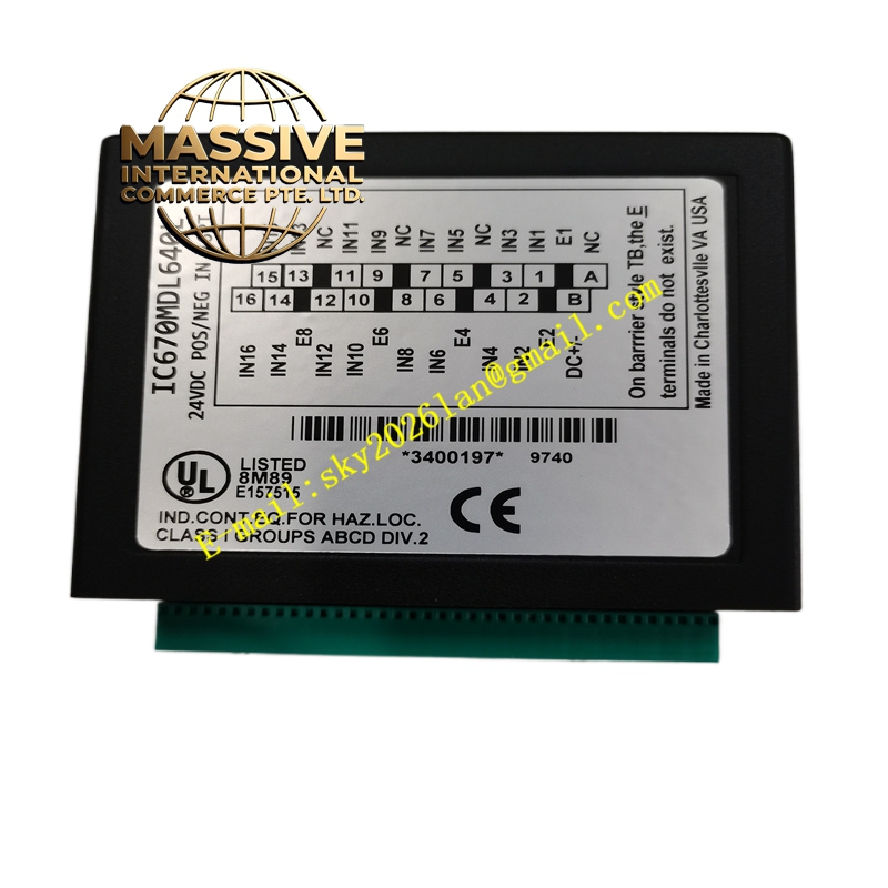
GE IC670MDL640
Technical Specifications:
| Parameter | Specification |
|---|---|
| Product Line | Field Control Series |
| Module Type | Discrete Input Module |
| Number of Channels | 16 Input Points |
| Input Logic | Positive/Negative selectable |
| Input Voltage | 0-30VDC nominal 24VDC |
| User Input Current | 7.5mA per point |
| On-Voltage | +15 to +30VDC (positive) / -15 to -30VDC (negative) |
| Response Time | <2ms |
| Power Consumption | 83mA total active consumption |
Functional Features:
- Receives digital signals from switches, sensors, and external devices
- Supports positive and negative logic configurations
- LED indicator per input point for status monitoring
- High-density 16-point I/O in compact form factor
- Field-installable module design
- Can function as expansion input alongside BIU module
Application Scenarios:
- Digital sensor interface applications
- Switch status monitoring systems
- Position detection circuits
- Limit switch interfacing
- Safety system inputs
- Machine status indicators
- Equipment state monitoring networks
Performance Parameters:
| Parameter | Value |
|---|---|
| Operating Voltage | 24VDC nominal |
| Input Voltage Range | 0-30VDC |
| Conducting Current | 3.0-8mA |
| Cut-off Current | 0-1.5mA |
| Surge Voltage | 250V AC/DC withstand |
| Isolation | 1500VAC 1min between input and ground |
| Working Temperature | -20°C to +70°C |
| Storage Temperature | -40°C to +85°C |
| Humidity | 5% to 95% non-condensing |
Construction Characteristics:
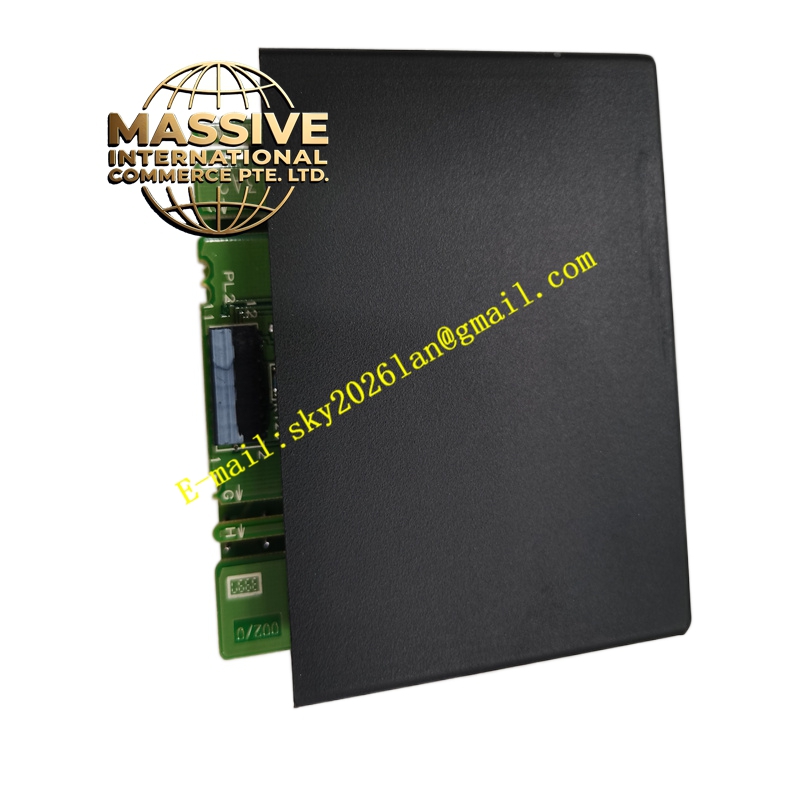
- Compact DIN-rail mountable design
- Front terminal block for field wiring
- Individual LED indicators for each point
- Robust plastic/metal hybrid housing
- Keypad feature for special programming
- CE and UL compliant manufacturing standards
Installation Requirements:
- Install adjacent to Bus Interface Unit in rack
- Connect field devices to terminal block appropriately
- Select logic type (positive/negative) per system design
- Provide clean 24VDC power supply
- Ground system per NEC and local code requirements
Usage Precautions:
- Verify logic polarity matches field device configuration
- Do not exceed input voltage ratings
- Protect against electrical transients with surge suppression
- Use wire gauge appropriate for current ratings
- Inspect connectors periodically for wear or damage