Description
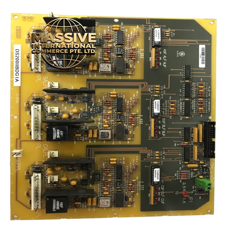
GE DS200IIBDG1A
- Technical Specifications:
- Channels: 32 discrete input channels organized into 2 groups of 16 channels each
- Input Voltage: 24 VDC nominal (accepts 12–30 )
- Input Type: Sinking (NPN) or sourcing (PNP) configurable per group via jumper or software
- Isolation: 500 VDC between Group A and Group B; 500 between each group and logic (backplane)
- Optical Isolation: High-speed optocouplers with 5 kVDC withstand voltage per channel
- Input Filter: 1 ms to 100 ms software-configurable debounce filter per group
- Scan Rate: 10 ms per group (20 ms total for all 32 channels)
- Current per Channel: 5 mA typical input current at 24 VDC
- Accuracy: Not applicable (discrete input); state detection accuracy ±1 ms
- Diagnostics: Per-channel LED indicators; group-level fault LED; backplane communication status LED
- Functional Features:
- Dual Group Isolation: The two 16-channel groups are completely isolated from each other, allowing one group to be connected to 120 VAC field devices (via an external interface relay) while the other group connects to 24 devices, all on the same board
- Configurable Input Type: Each group can be independently set to sinking (NPN) or sourcing (PNP) without hardware changes
- Software Debounce: Adjustable debounce time from 1 ms to 100 ms eliminates contact bounce from mechanical switches and relay chatter
- Fail-Safe Monitoring: The board continuously monitors input wire integrity; an open circuit or short circuit on any channel is flagged as a fault
- Hot Swap: Designed for live insertion and removal in redundant Mark V/VI configurations
- Application Scenarios:
- Steam Turbines: Turbine stop valve position, governor oil solenoid status, emergency trip pushbutton status, bearing oil pump run status
- Gas Turbines: Igniter status, fuel valve position, inlet guide vane position, compressor bleed valve status
- Generators: Breaker open/close status, field breaker status, alarm contacts, protection relay outputs
- BOP (Balance of Plant): Pump run/stop status, valve open/close status, motor starter feedback, level switch status
- Industrial Process: Conveyor run status, gate valve position, hopper level switches, safety interlock contacts
- Performance Parameters:
- Operating Temperature: 0°C to 60°C
- Storage Temperature: -40°C to 85°C
- Relative Humidity: 5% to 95% non-condensing
- Power Consumption: 2.8 W typical
- MTBF: Greater than 180,000 hours
- EMC Compliance: IEC 61000-6-2, IEC 61000-6-4
- Material & Structure:
- Form Factor: Mark V/VI standard board, approximately 170 mm × 100 mm × 25 mm
- Connectors: 40-pin backplane connector; 2 × 20-pin field terminal blocks (one per group) on the top of the board
- PCB: 6-layer FR-4 with conformal coating
- Enclosure: Zinc-plated steel chassis with EMI shielding
- Weight: Approximately 300 grams
- Front Panel: 32 green LEDs (one per channel, grouped in two sets of 16); 2 amber fault LEDs; 1 green power LED
- Working Principle:
- Each input channel consists of an optocoupler with a series current-limiting resistor. When a 24 VDC signal is applied to the input, current flows through the optocoupler’s LED, activating the phototransistor on the logic side. The phototransistor output is buffered by a Schmitt trigger for noise immunity, then latched by a flip-flop that is sampled by the Mark V/VI CPU every 10 ms per group. The isolation barrier (optocoupler) provides 500 galvanic separation between the field side and the logic side. The debounce filter is implemented in software within the controller, counting consecutive identical samples before accepting a state change.
- Installation Requirements:
- Rack: Mark V or Mark VI I/O rack; install in any standard I/O slot
- Wiring: Use shielded cable for each group; connect shield to chassis ground at the control system end only
- Input Type Configuration: Set the sinking/sourcing jumper on the board (or configure via software in Mark VI) to match the field device type before applying power
- Terminal Blocks: The field wiring connects to 20-pin terminal blocks; ensure wire gauge is 18–22 AWG for reliable contact
- Group Separation: Keep Group A and Group B wiring physically separated in the field to maintain isolation integrity
- Usage Notes:
- Do not apply more than 30 VDC to any input channel; overvoltage will destroy the optocoupler
- Sinking vs. Sourcing: For sinking (NPN) inputs, the field device switches the negative side; for sourcing (PNP) inputs, the field device switches the positive side. Incorrect configuration will result in all inputs reading as OFF
- Debounce Setting: Set debounce to 10–20 ms for mechanical switches; set to 1–2 ms for solid-state proximity sensors
- Wire Fault Detection: The board detects open circuits (input reads OFF when it should read ON) and short circuits (input reads ON when it should read OFF); both conditions generate a diagnostic alarm
- Replacement: When replacing a failed board, verify the new board’s hardware revision matches the system configuration; BNC and BKC revisions are not interchangeable with the original A revision in all cases