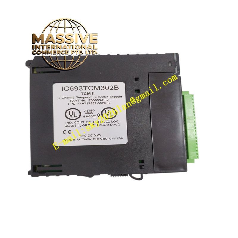
Description
GE IC693TCM302 Technical Specifications:
- Input Type: Thermocouple (J, K, T, E, N, R, S, B, C, and mV).
- Channels: Multiple independent thermocouple input channels.
- Resolution: High-resolution Analog-to-Digital Converter (ADC).
- Isolation: Channel-to-channel and channel-to-backplane galvanic isolation.
- Update Rate: Fast scan rate for real-time temperature tracking.
Functional Features:
- Direct Thermocouple Interface: Eliminates the need for external signal conditioners.
- Open Thermocouple Detection: Built-in diagnostics to detect broken sensor wires.
- Software Configuration: Thermocouple type and scaling configured via PLC programming software.
- Cold Junction Compensation: Internal temperature compensation for accurate readings.
Application Scenarios:
- Industrial furnace and oven temperature control.
- Chemical reactor monitoring.
- HVAC and environmental testing chambers.
- Food and beverage pasteurization processes.
Performance Parameters:
- Accuracy: High-precision measurement with low drift over temperature.
- Input Impedance: High impedance to prevent loading of the thermocouple signal.
- Noise Rejection: Excellent common-mode and normal-mode noise rejection.
- Response Time: Rapid digital filtering and update rates.
Material Composition & Structural Characteristics:
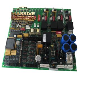
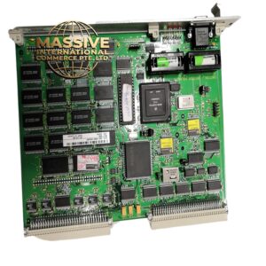
- PCB: Precision analog circuit board with low-thermal-EMF components.
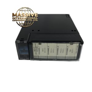
- Connectors: Removable terminal blocks for easy field wiring.
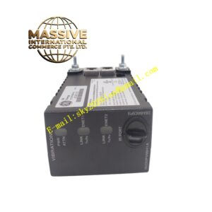
- Housing: Standard Series 90-30 module enclosure.
- Status LEDs: Channel-specific indicators for fault and status monitoring.
Working Principle: The module measures the minute millivolt signals generated by the thermocouples. Internal cold junction compensation sensors measure the temperature at the module’s terminals to correct the reading. The analog signals are amplified, filtered, and digitized by the ADC. The microprocessor applies the selected thermocouple polynomial to convert the voltage into an engineering temperature unit.
Installation Requirements:
- Wiring: Use properly matched thermocouple extension wire to prevent dissimilar metal junctions.
- Shielding: Use shielded twisted-pair wire and ground the shield at the module end only.
- Separation: Route thermocouple wires away from high-voltage AC lines and motor leads.
- Configuration: Set the correct thermocouple type in the PLC software before commissioning.
Usage Precautions:
- Polarity: Observe strict polarity when wiring thermocouples; reversed leads will cause negative temperature readings.
- Ground Loops: Do not ground the thermocouple at both the sensor and the module to prevent ground loop errors.
- Module Limits: Do not apply voltages exceeding the module’s maximum input rating.
- Calibration: Periodically verify accuracy using a precision millivolt calibrator.