Description
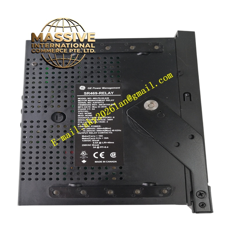
GE SR469-P5-HI-A20
Technical Specifications:
- Series: GE Multilin SR469 Motor Management Relay
- Phase CT Secondary: 5 A (P5)
- Control Power: HI = 90–300 V DC, 70–265 V AC, 48–62 Hz
- Analog Output: 4–20 mA (A20), four analog outputs
- Display: Basic (no enhanced LCD)
- Communication: RS-232 program port (9600–19,200 baud), RS-485
- Ground CT Inputs: Two (one for GE source-ground management, one for ground CT)
- VT Input: Delta or wye configurations
- Drawout Construction: Yes
- Conformal Coating: No
- Certifications: CE marked
Functional Features:
- Comprehensive motor protection: thermal overload, overcurrent, undervoltage, overvoltage, phase imbalance, ground fault, stall, locked rotor
- Voltage-compensated acceleration protection
- VT inputs for voltage and power protection
- CT inputs for phase differential protection
- Four 4–20 mA analog outputs for SCADA telemetry
- Event recording and oscillography
- Drawout construction for rapid replacement
- Field-upgradable firmware
- EnerVista software integration
Application Scenarios:
- Medium-voltage motor protection in industrial automation
- Power generation plant auxiliary motor management
- Steel mills, cement plants, chemical and paper industries
- Pump, fan, and compressor motor protection
Performance Parameters:
- Comprehensive metering: A, V, W, var, VA, PF, Hz, Wh, varh, demand, torque, temperature, trending
- Advanced thermal model with unbalance bias
- Fast-acting protection elements
- CE-certified for European installations
Material and Structural Characteristics:
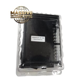
- Drawout relay case with matching enclosure
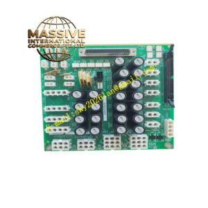
- Industrial-grade PCB with high-reliability components
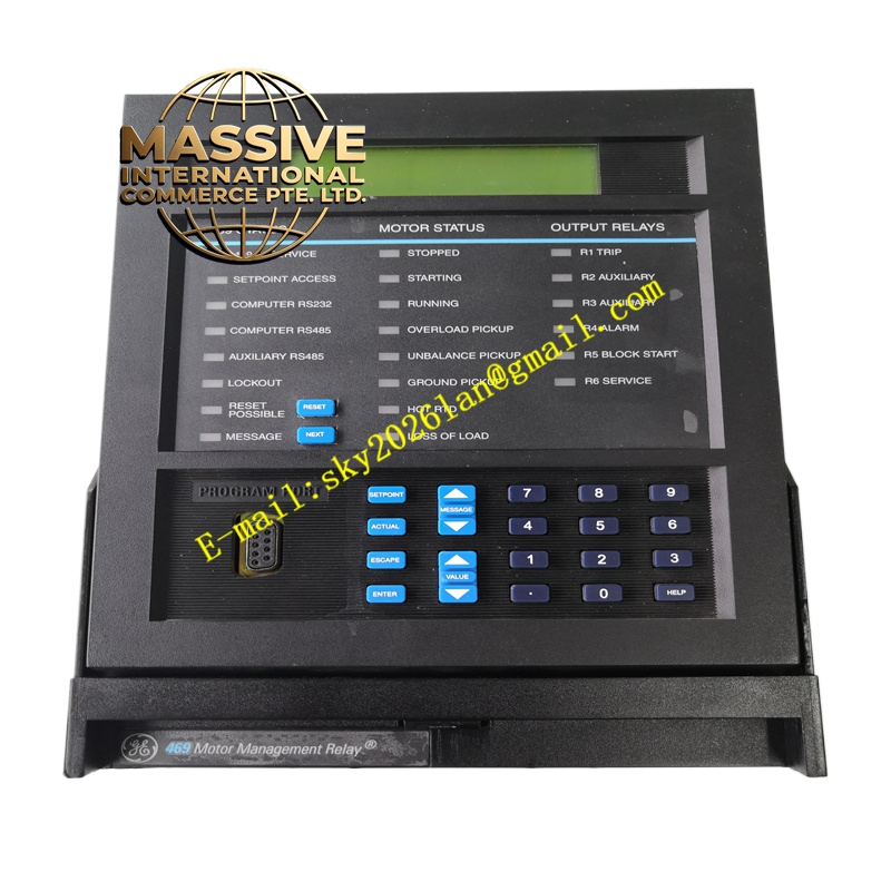
- Front panel with basic display, status LEDs, keypad, and programming keys
- RS-232 program port on front panel
- Sealable drawout handle
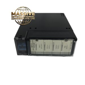
- Rear terminal blocks for CT, VT, control power, and I/O
Working Principle: Identical to other SR469 variants. The relay samples phase currents (5 A CT secondary), voltages, and ground fault currents, executes protection algorithms, and trips the motor breaker when setpoints are exceeded. The thermal capacity model integrates stator heating, unbalance bias, and RTD feedback for accurate motor thermal protection. Installation Requirements:
- Install in a protection relay panel using the SR drawout case
- Connect 5 A phase CTs, VTs (delta or wye), and ground CT
- Wire control power (90–300 V DC or 70–265 V AC)
- Connect RS-232/RS-485 to SCADA
- Configure setpoints using EnerVista 469 Setup software
Usage Notes:
- Verify CT secondary rating (5 A) matches installed CTs
- Apply thermal model and K-factor per motor characteristics
- Use the sealable drawout handle for security
- Periodically test protection functions and verify analog output calibration