Description
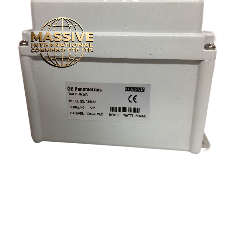
GE BJZCAT868-1
Technical Specifications:
- Type: Power distribution terminal block with fused taps
- Rated Voltage: 250V AC / 125V DC
- Rated Current: 10A per circuit (continuous)
- Short-Circuit Rating: 10kA at 250V DC
- Number of Circuits: 8 to 12 poles (depending on variant)
- Fuse Type: 5x20mm glass tube fuses (500mA to 10A selectable)
- Fuse Indicator: Mechanical flag indicator for blown fuse detection
- Terminal Type: Spring-clamp (push-in) terminals
- Wire Size: 0.5mm² to 4mm² (AWG 20 to AWG 12)
- Grounding: Dedicated copper ground bar with 4 connection points
- Surge Protection: Compatible with DIN rail surge suppressors (plug-in)
- Operating Temperature: -25°C to +70°C
- Enclosure Material: Flame-retardant polycarbonate (UL94 V-0)
- Dimensions: Approximately 200mm x 80mm x 70mm (H x W x D)
- Weight: Approximately 0.6kg
- Standards: UL listed, CSA certified, IEC 60947-7-1, CE marked
Functional Features:
- Provides individual fused protection for each relay and I/O module circuit
- Spring-clamp terminals allow tool-free wiring and quick disconnection
- Clear circuit labeling strips for easy identification of each feed
- Ground bus bar ensures all equipment is bonded to panel ground
- Surge protection module slots allow addition of transient voltage suppressors
- Visual fuse status indicator on each circuit for quick troubleshooting
- Modular design allows stacking multiple units for larger panels
- Rear cable entry with PG gland connectors for clean cable routing
Application Scenarios:
- GE Multilin relay panel internal power distribution
- Control cabinet DC power bus bars for PLC and relay systems
- Industrial automation enclosures requiring clean power segmentation
- Substation DC control panels (battery-fed)
- Marine vessel control panels with vibration-resistant wiring
Performance Parameters:
- Contact Resistance: Less than 5mΩ per terminal
- Insulation Resistance: Greater than 100MΩ at 500V DC
- Dielectric Strength: 2000V AC for 1 minute between circuits
- Mechanical Life: 10,000 insertion/removal cycles (spring terminals)
- Vibration Resistance: IEC 60068-2-6 compliant (10Hz to 150Hz, 2g)
Material Composition:
- Housing: Polycarbonate with 30% glass fiber reinforcement
- Terminals: Copper alloy (C17200 beryllium copper) with tin plating
- Ground Bar: Electrolytic tough pitch copper (ETP Cu) with tin plating
- Fuse Holder: Ceramic with nickel-plated contacts
- Labeling: Laser-etched polycarbonate strips (permanent, chemical resistant)
Structure Features:
- DIN rail mount (35mm) with snap-in clips
- Front-accessible fuse replacement without removing the unit
- Rear cable entry with 4 x PG11 glands (for 4mm² cables)
- Modular width allows 2, 3, or 4 units side-by-side
- Color-coded fuse holders: red for critical circuits, yellow for standard
Working Principle: Main DC bus power enters the unit from the top or rear. Each circuit is protected by an individual fuse. The spring-clamp terminals distribute power to downstream devices (relays, I/O modules). The ground bar bonds all equipment chassis to the panel ground. If a short circuit occurs on any branch, only that fuse blows, isolating the fault without affecting other circuits. Installation Requirements:
- Mount on DIN rail at the top or side of the relay panel
- Connect main bus power to the input terminals (use 4mm² cable minimum)
- Connect each branch circuit to the output terminals (use 1.5mm² cable)
- Bond the ground bar to the panel ground bus using 6mm² green/yellow cable
- Install surge protection modules in the dedicated slots if required
Usage Notes:
- Always install the correct fuse rating for each circuit (do not oversized)
- Do not bypass fuses under any circumstances
- Check fuse indicators monthly during routine maintenance
- Ensure all grounding connections are tight (torque to 0.8Nm)