Description
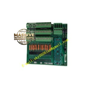
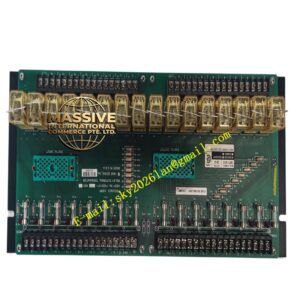
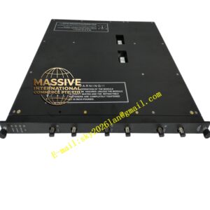
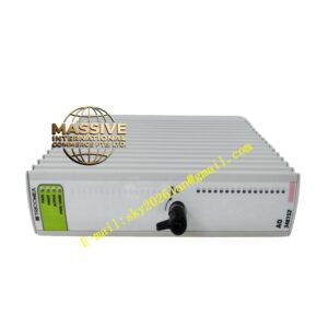
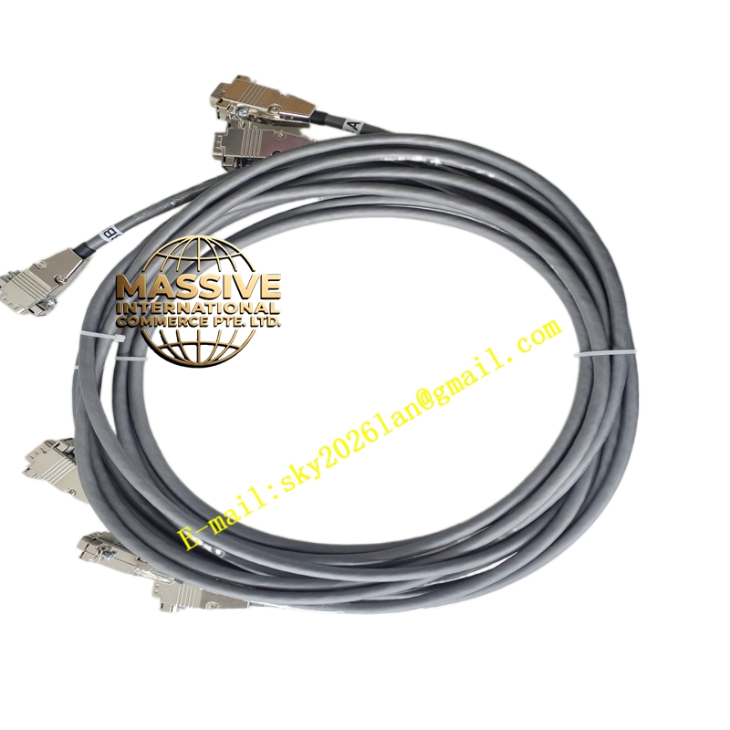
Triconex 4000153-010
Technical Specifications:
- Type: External termination/cable assembly
- Length: Application-specific (verify per system documentation)
- Connectors: Triconex-specific keyed connectors
- Voltage rating: Compatible with Triconex low-voltage I/O (typically 24 V DC; consult manuals)
- Current rating: As per associated I/O module and terminal board ratings
- Operating temperature: 0 °C to 60 °C (per Tricon system specs)
- Shielding: Options available for noise-sensitive applications
- Materials: Industrial-grade insulation and jacketing
Functional Features:
- Pre-engineered for Triconex systems to ensure compatibility
- Supports power, signal, and communication connections
- Reduces field wiring errors and commissioning time
- Designed for harsh industrial environments
Application Scenarios:
- Interconnecting Triconex I/O modules with external terminal panels
- Used in safety-critical applications such as ESD, F&G, BMS, HIPPS
- Suitable for environments requiring reliable, shielded signal paths
Performance Parameters:
- Maintains signal integrity across specified lengths
- Supports required communication protocols and data rates
- Durable construction for long service life
Material and Structural Characteristics:
- Conductors: Copper strands
- Insulation/jacket: Thermoplastic resistant to oils and chemicals
- Shielding (if applicable): Braided/foil with drain wire
- Connector housings: Robust materials with metal shielding where needed
Working Principle: The assembly carries signals between Triconex modules and field devices/terminal panels. Shielded versions minimize electromagnetic interference. Keyed connectors ensure correct mating and secure electrical contact. Installation Requirements:
- Route cables away from sources of electrical noise
- Secure properly to avoid strain on connectors
- Ensure connectors are fully seated
- Follow Triconex guidelines for bend radius and protection
Usage Notes:
- Inspect for damage before installation
- Use only Triconex-specified assemblies for safety-certified systems
- Replace if wear or damage is detected
- Maintain environmental conditions within specified limits