Description
Triconex 9771-210F Technical Specifications:
- Input Type: Discrete Digital Inputs (Dry Contact, Sourcing, or Sinking).
- Voltage Ratings: Typically supports 24 VDC or 120 VAC field inputs (verify specific variant).
- Channel Count: Multiple isolated digital input channels per module.
- Safety Integrity: Designed to meet SIL 3 (Safety Integrity Level 3) requirements.
- Response Time: Fast, deterministic response time for critical safety trip detection.
Functional Features:
- TMR Input Architecture: Each input channel is read independently by three separate internal circuits, allowing the system to vote out a faulty sensor or internal component.
- Field Power Monitoring: Continuously monitors the health and voltage levels of the external field power supply.
- Advanced Filtering: Configurable software and hardware input filters to reject electrical noise, contact bounce, and transient spikes.
- Comprehensive Diagnostics: Detects open wires, short circuits to ground/power, and internal IC failures, reporting them instantly to the host controller.
Application Scenarios:
- Safety-critical limit and position monitoring for emergency shutdown valves.
- High-pressure and high-temperature switch monitoring in chemical reactors.
- Permissive and interlock signal acquisition in combustion systems.
- Manual emergency pushbutton and pull-cord station inputs.
Performance Parameters:
- Input Impedance: High impedance to minimize loading on field devices.
- Isolation: Full galvanic isolation between field inputs and the internal safety backplane.
- Accuracy: 100% accurate state detection with zero false-trip tolerance.
- Update Rate: Synchronized with the main TMR processor scan rate for deterministic safety logic execution.
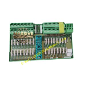
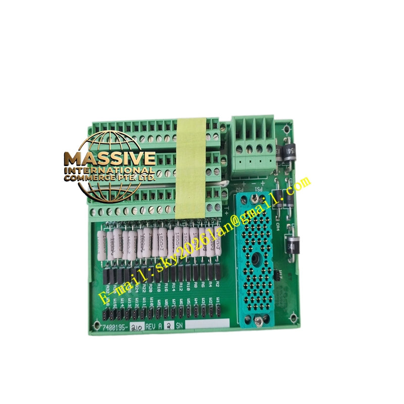
Material Composition & Structural Characteristics:
- Opto-Isolators: High-reliability optical isolators to provide complete electrical separation between field hazards and internal logic.
- PCB Construction: Conformal-coated multi-layer PCB to protect against moisture, sulfur, and corrosive industrial gases.
- Terminals: Robust, high-current terminal blocks or front-access connectors designed for secure field wiring.
- Status Indicators: Individual front-panel LEDs for each channel to provide immediate local visual confirmation of field device states.
Working Principle: Field voltage or contact closure is applied to the module’s input terminals. The signal passes through protection circuitry and is fed into three independent opto-isolator circuits. The internal microcontroller reads the state of all three circuits. If two or more agree, that state is accepted as valid. If a discrepancy occurs, the module flags a diagnostic fault, allowing the system to safely determine whether to trip or continue operating.
Installation Requirements:
- Wiring: Use properly rated, insulated copper wire. Ensure field power supplies are isolated and appropriately fused.
- Grounding: Ground the module chassis and shield drains correctly to prevent ground loops and noise ingress.
- Termination: Verify tight terminal connections; loose wires can cause intermittent faults that mimic safety trips.
- Software Mapping: Accurately map the physical channel addresses to the safety logic tags in the TriStation configuration.
Usage Precautions:
- Never Bypass Diagnostics: Do not force or mask diagnostic alarms without a formal, documented safety management procedure.
- Field Wiring Safety: Treat all field wiring as potentially hazardous; verify de-energization before making changes.
- Spare Parts: Maintain calibrated, identical spare modules to minimize Mean Time To Repair (MTTR) during a failure.
- Testing: Perform regular proof tests as dictated by the Safety Requirements Specification (SRS) to verify the module’s ability to detect dangerous failures.