Description
Triconex 9556-810F Technical Specifications:
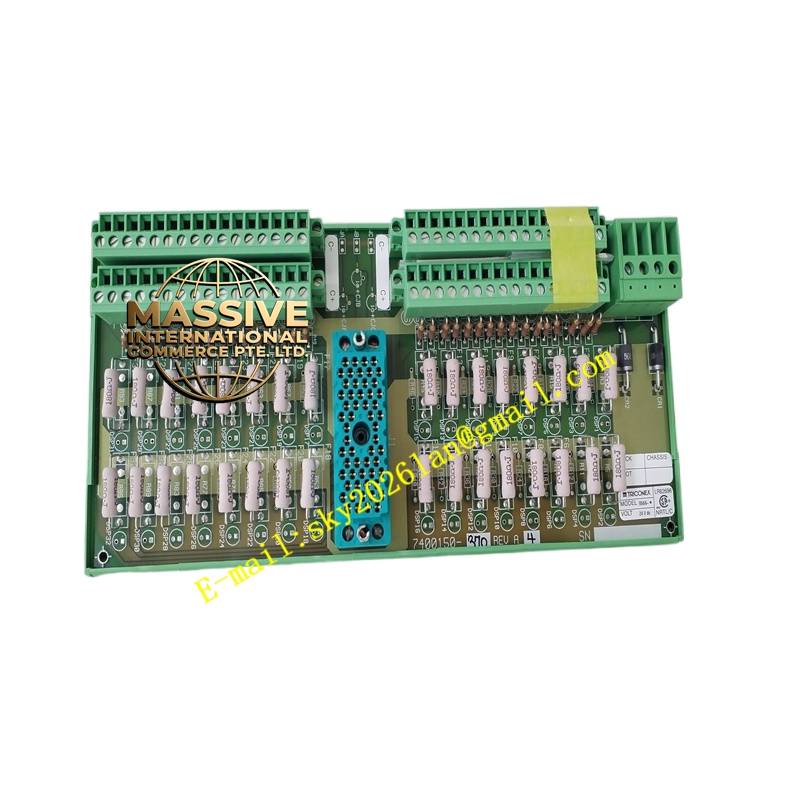
- Field Wiring Interface: Screw terminals for field signal connections.
- Module Compatibility: Mates with specific Tricon digital input modules (e.g., 3501E, 3503E).
- Signal Type: Dry contact, wet contact, or solid-state inputs.
- Voltage Rating: Compatible with 24VDC, 48VDC, or 115VAC/DC field signals depending on the mated module.
Functional Features:
- Signal Conditioning: Provides primary filtering and transient suppression for field signals.
- Diagnostic Support: Supports loop-back diagnostics to verify field wiring integrity.
- Isolation: Galvanic isolation between field wiring and backplane.
- Labeling: Pre-printed terminal identification for simplified wiring and maintenance.
Application Scenarios:
- Interfacing limit switches, pressure switches, and level switches.
- Connecting safety pushbuttons and ESD station triggers.
- Field signal marshalling in safety instrumented systems.
Performance Parameters:
- Contact Rating: Rated for continuous industrial current loads.
- Dielectric Strength: High isolation voltage to protect against field surges.
- Vibration Resistance: Designed to withstand harsh industrial environments.
Material Composition & Structural Characteristics:
- Base Material: Flame-retardant thermoplastic housing.
- Terminals: High-conductivity copper alloy screw terminals with tin plating.
- PCB: Multi-layer board with surface-mount protection components.
- Mounting: DIN rail or chassis mount design.
Working Principle: Field wires are terminated on the 9556-810F screw terminals. The terminal board routes these signals through protection circuits (fuses, MOVs) to the backplane connector. When mated with a digital input module, the module reads the state of the field signal through the terminal board’s contacts.
Installation Requirements:
- Wiring: Use properly crimped ferrules or spade lugs for secure connections.
- Torque: Tighten terminal screws to the manufacturer’s specified torque to prevent hot spots.
- Shielding: Connect signal shields to the designated shield terminal if applicable.
- Alignment: Ensure proper alignment with the I/O module before pressing together.
Usage Precautions:
- De-energize: Always de-energize field circuits before wiring or modifying connections.
- Wire Size: Strictly adhere to the recommended wire gauge range for the terminals.
- Inspection: Periodically check terminal tightness during preventive maintenance.
- Compatibility: Verify the terminal board part number matches the I/O module specifications.