Description
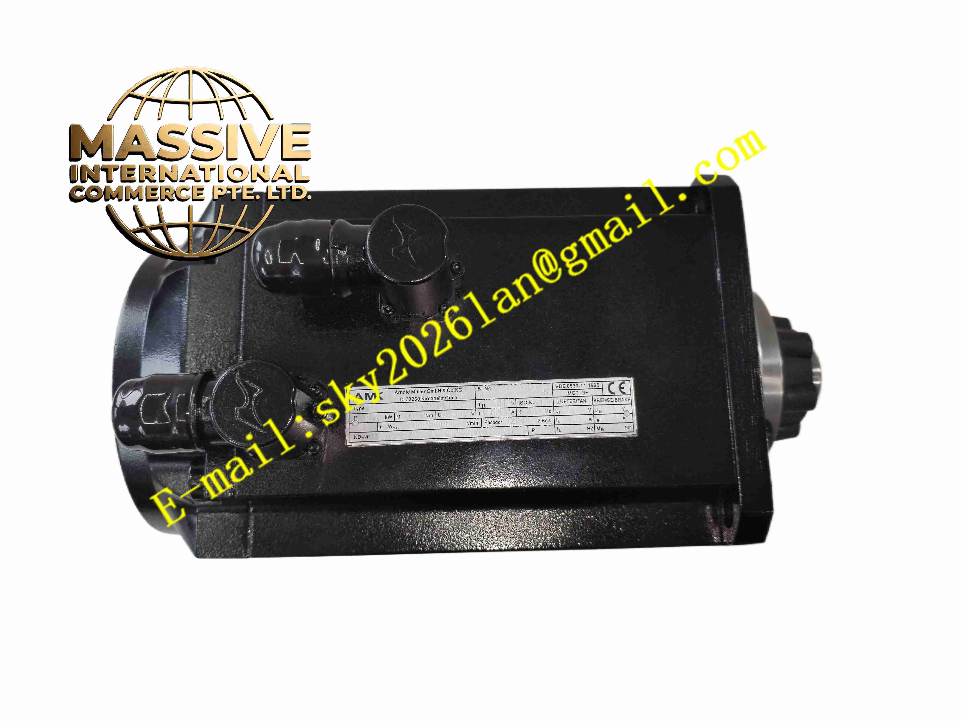
AMK DT7-17-20-E00 A2525CD
Technical Specifications
- Product Type: Permanent magnet synchronous AC servo motor
- Cooling Method: Natural convection cooling
- Flange Size: 100 mm
- Rated Torque: 17 Nm
- Rated Speed: 3000 rpm
- Max Speed: 5000 rpm
- Feedback Device: EnDat 2.2 encoder
- Brake Configuration: Integrated electromagnetic holding brake
- Protection Class: IP54, optional IP65
- Insulation Class: F class
- Operating Temperature: -20 °C to +40 °C
- Certification: CE, CSA, UL
Functional Features
- High torque density design delivers large continuous torque at compact frame size.
- Overmolded rotor permanent magnet structure protects magnets from dust and moisture.
- High-resolution EnDat encoder provides accurate position and speed feedback.
- Integrated holding brake maintains shaft position when power supply is lost.
- Low cogging torque ensures smooth operation at low rotating speed.
- High dynamic response supports fast acceleration and deceleration cycles.
- F-class winding insulation withstands high continuous operating temperature.
- Robust bearing structure resists mechanical vibration in machine operation.
- Single cable wiring option simplifies on-site wiring layout.
- Compatible with AMK series servo drives for full closed-loop motion control.
Application Scenarios
- CNC machine tool feed axes
- Automated robotic handling axes
- Packaging machinery high-speed positioning
- Material cutting and laser processing equipment
- Printing machinery high precision drive systems
Material Composition
- Motor housing: Die-cast aluminum alloy with cooling ribs
- Stator: Silicon steel lamination stack with high-temperature enameled wire winding
- Rotor: High-energy rare earth permanent magnet embedded in overmolded plastic
- Output shaft: Quenched and tempered alloy steel
- Bearings: Precision sealed ball bearings
- Brake component: Electromagnetic friction holding brake
- Encoder housing: Aluminum alloy shell
Structural Characteristics
- Cylindrical aluminum housing with external cooling ribs for heat dissipation.
- Front end equipped with output shaft and flange mounting surface.
- Rear end integrated with high-resolution rotary encoder.
- Electromagnetic holding brake installed between stator and encoder section.
- Separate power connector and encoder feedback connector on motor side.
- Internal winding and rotor components sealed to meet IP54 protection rating.
Working Principle The servo drive outputs three-phase variable frequency AC current to the stator winding, generating rotating magnetic field. The permanent magnet rotor follows the rotating magnetic field to produce torque and drive the load. The rear-end EnDat encoder continuously transmits rotor position and speed data back to servo drive. The drive adjusts output current and frequency in real time to realize closed-loop position, speed and torque control. When power cuts off, the electromagnetic holding brake engages to lock the motor shaft and prevent load movement.
Installation Requirements
- Flange mounting with precise coaxial alignment between motor shaft and load.
- Use flexible coupling to connect motor shaft and load to reduce vibration stress.
- Reserve enough space around motor housing for natural convection heat dissipation.
- Use shielded power cable and shielded encoder cable, single end shield grounding.
- Perform manual rotation test before power-on to confirm no mechanical jamming.
- Verify wiring definition of power and encoder connectors to avoid miswiring.
- Complete protective earth connection with low resistance grounding path.
Usage Notes
- Do not exceed rated continuous torque and maximum speed.
- Do not apply heavy radial or axial impact load directly to output shaft.
- Encoder cable must be routed separately from high-power power cables.
- Regularly inspect bearing noise and coupling tightness.
- Disconnect motor and encoder wiring before insulation resistance test.
- Long-term storage environment must be dry, perform periodic dehumidification energization.
- Avoid continuous operation above ambient temperature limit.