Description
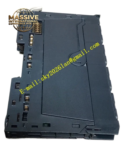
Emerson EP-3164
Technical Specifications: Power supply: 24 VDC Number of controllable axes: up to 64 axes Internal bus: high-speed motion control backplane bus Program storage: non-volatile flash memory Data memory: high-speed RAM for real-time operation Operating temperature: 0 ℃ to 55 ℃ Storage temperature: -40 ℃ to 85 ℃ Relative humidity: 5% to 95% non-condensing
Functional Features: Supports linear interpolation, circular interpolation and helical interpolation. Built-in electronic cam function for phase synchronization between axes. Supports master-slave axis following and flying shear control. Hardware high-speed bus ensures synchronous command transmission. Complete program online monitoring and online modification. Built-in hardware watchdog triggers safe state on processor fault. Comprehensive self-diagnosis for bus communication and memory status. Hot-swap design supports online replacement.
Application Scenarios: Large printing press multi-axis synchronous control, packaging production line flying shear system, textile spinning equipment motion control, metal processing cutting machine, automated palletizing robot auxiliary axis control, continuous material processing production line.
Performance Parameters: Motion command cycle: 0.25 ms minimum Vibration resistance: 10 Hz to 150 Hz, 0.5 g Shock resistance: 10 g peak acceleration, 11 ms duration MTBF value: 192000 hours
Material Composition: Module housing: UL94-V0 flame-retardant engineering plastic. Main PCB: FR-4 glass fiber epoxy substrate. Backplane connector pins: gold-plated copper alloy. Industrial embedded processor and memory chips. Side locking latches use reinforced engineering plastic.
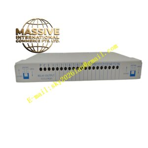
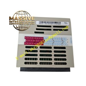
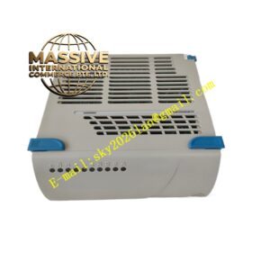
Structural Features: Standard rack plug-in module structure. Two side locking latches fix module on rack backplane. Front panel has LED indicators for power, run, fault and bus status. Ventilation grille on top shell for passive heat dissipation. Rear multi-pin gold-plated connector connects rack backplane power and motion bus.
Working Principle: After power-on, the module loads user motion program stored in flash memory. It reads system parameters and axis status from each servo drive module via backplane bus. It calculates motion trajectory according to program instructions and generates target position command for each axis. It transmits command data to corresponding servo amplifiers. It continuously collects axis feedback status and alarm information. When main processor fails, watchdog circuit stops all motion output to safe state.
Installation Requirements: Insert module into designated processor slot of motion control rack and fully lock side latches. Reserve vertical clearance above and below module for heat dissipation. Separate motion signal cables and high-power power cables. Cut off rack power before plugging or removing module.
Precautions for Use: Do not download untested motion program into running system. Wear anti-static wristband during maintenance. Regularly clean dust on ventilation grille. Avoid installation in environment with conductive dust and corrosive vapor. Replace module immediately if bus communication keeps abnormal.