Description
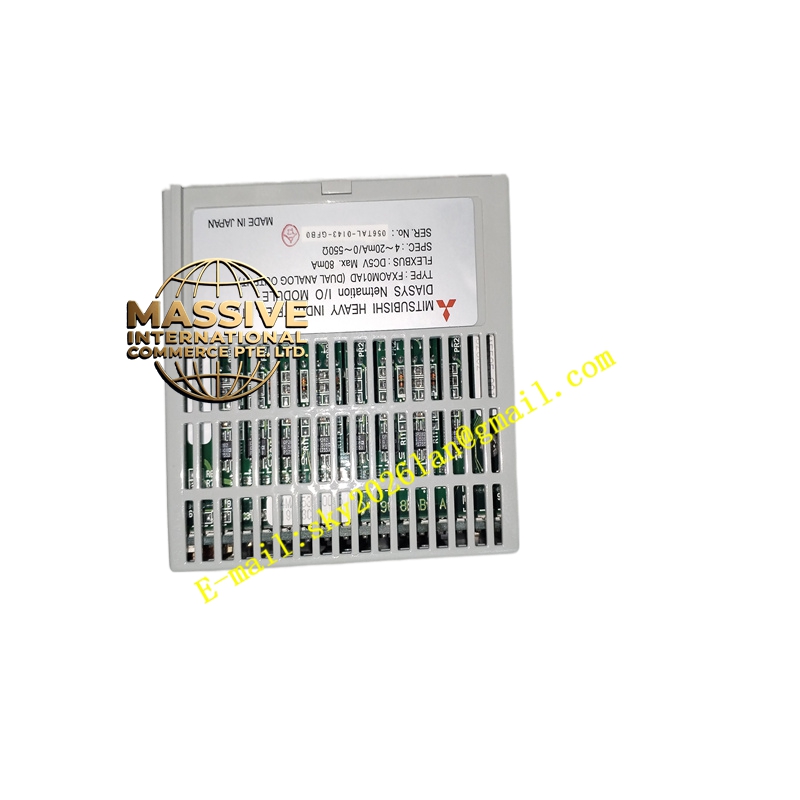
Foxboro FXAOM01AD Technical Specifications:
- Output Channels: Typically 4 or 8 isolated analog outputs (verify with specific datasheet)
- Output Signal Types: 4–20 mA, 0–20 mA, 0–10 V, ±10 V (configuration depends on TA)
- Accuracy: ±0.1% of span or better (typical for I/A Series AO modules)
- Resolution: 16-bit D/A conversion (typical)
- Isolation: Channel-to-channel and channel-to-ground isolation for noise immunity and safety
- Update Rate: Synchronized with I/A Series control scan (typically sub-second)
- Communication: 2 Mbps module fieldbus to the FCP270/FCP280
- Power: 24 V DC from the baseboard
- Environment: 0 °C to 60 °C; 5%–95% RH non-condensing (G3 compliant)
- Certifications: CE; hazardous area options available
Functional Features:
- High-precision D/A conversion for accurate analog control
- Supports output feedback/readback for selected channels (depending on TA)
- Per-channel diagnostics including open-circuit and short-circuit detection
- Configurable output ranges and fail-safe states (e.g., output to predetermined safe level on fault)
- Hot-swappable when used with redundant baseboard and terminal assemblies
Application Scenarios:
- Control valve positioning via current outputs (4–20 mA)
- Speed reference signals for VFDs or actuators via voltage outputs
- Modulating control in continuous processes (flow, pressure, temperature)
- Any process requiring reliable, isolated analog control signals
Performance Parameters:
- Low drift and high stability over temperature variations
- Fast update ensures responsive control
- High load drive capability (typical loop impedance up to 600 Ω)
Material and Structural Characteristics:
- Industrial PCB with precision analog front-end and isolation components
- Robust metal front panel with status LEDs
- Pluggable connectors to baseboard/TA for easy wiring and replacement
- Conformal coating for harsh environments
Working Principle: The module receives digital setpoint values from the control processor via the module fieldbus. Each channel’s D/A converter generates the analog signal, which is conditioned and isolated before being output to the field device through the Terminal Assembly. Diagnostics monitor output current and voltage, detecting open or short circuits and reporting faults. Installation Requirements:
- Mount into a compatible 200 Series baseboard/TA
- Connect field wiring from outputs to the controlled devices; observe polarity and shield grounding
- Configure output ranges, scaling, and fail-safe behavior via Foxboro engineering tools
- Verify loop power supply and impedance are within specifications
Usage Notes:
- Ensure load impedance and loop power supply match the selected output range to maintain accuracy
- Use shielded twisted-pair cables for analog outputs to reduce noise
- Perform regular loop checks to verify outputs match setpoints
- Do not exceed maximum output voltage and current ratings per channel