Description
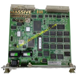
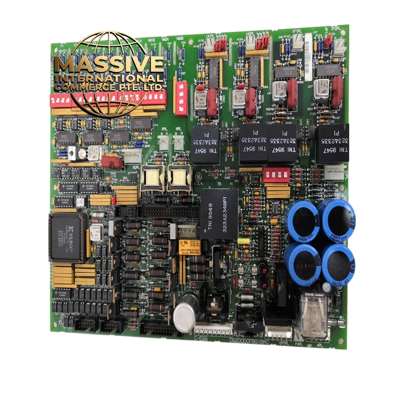
GE DS200DCFBG1BKC — Dual Channel Feedback Board, Mark VI/VIe
- Technical Specifications:
- Channels: 2 independent feedback input channels (Channel A and Channel B)
- Input Types Supported:
- Tachometer: AC tachometer (sine wave, 0–10,000 RPM) or DC tachometer (voltage proportional to speed, 0–5,000 )
- Resolver: 4-wire resolver with 4.25 VAC excitation at 50 Hz to 10 kHz
- Encoder: Quadrature encoder (A/B differential signals) with Z index pulse, frequency up to 1 MHz
- Tachometer Range: AC tachometer 0–10,000 RPM; DC tachometer 0–5,000
- Resolver Input: Excitation output 4.25 VAC ± 5% at 50 Hz, 400 Hz, or 2 kHz (user-selectable); resolver signal input range 0.1 VAC to 10 VAC
- Encoder Input: A/B differential signal, 5 VDC TTL compatible; maximum frequency 1 MHz; Z index pulse supported
- Resolution: 16-bit counter for speed measurement (0.015 RPM resolution at 10,000 RPM); 12-bit counter for position measurement
- Isolation: 500 VDC optical isolation per channel (channel-to-channel and channel-to-logic)
- Accuracy: ±0.01% of full scale for speed; ±1 count for position
- Update Rate: 1 ms typical for speed; 10 ms typical for position
- Functional Features:
- Speed Calculation: Hardware-based frequency-to-voltage conversion with a 32-bit accumulator and digital FIR filter for noise rejection; no CPU overhead required
- Direction Detection: Automatic direction sensing from encoder A/B phase relationship and resolver sine/cosine phase; direction flag updated every 1 ms
- Fail-Safe Behavior: Configurable fail-to-zero (speed goes to 0 on signal loss) or fail-to-last (speed holds last valid value); position can be configured to hold or ramp to zero
- Diagnostics: Per-channel LED indicators for signal present, fault, direction, and speed range; self-test on power-up verifies all signal paths
- Resolver R/D Conversion: High-precision resolver-to-digital converter with 12-bit angular resolution and automatic gain control
- Encoder Decoding: Hardware quadrature decoder with 4× counting (counts all four edges of A and B signals) for maximum resolution
- Application Scenarios:
- Steam Turbines: Governor speed feedback for load control; rotor position for synchronization and protection
- Gas Turbines: Compressor speed feedback, power turbine speed for fuel control, starter motor position
- Generators: Rotor position and speed for synchronization with the grid; breaker close timing
- Large Motors: Variable frequency drive (VFD) speed feedback for closed-loop control
- Hydro Turbines: Runner speed feedback for governor control; guide vane position verification
- Wind Turbines: Generator speed feedback for pitch control (in GE wind applications)
- Performance Parameters:
- Operating Temperature: 0°C to 60°C (standard); extended range -10°C to 70°C available with derating
- Storage Temperature: -40°C to 85°C
- Relative Humidity: 5% to 95% non-condensing
- Power Consumption: 3.2 W typical
- MTBF: Greater than 200,000 hours at 40°C ambient
- Vibration: 2 g peak, 5–500 Hz (compliant with IEC 60068-2-6)
- EMC Compliance: IEC 61000-6-2, IEC 61000-6-4
- Material & Structure:
- Form Factor: Standard Mark VI/VIe board size, approximately 180 mm × 120 mm × 15 mm
- Connectors: 2 × 15-pin D-sub connectors for field inputs (one per channel); 64-pin backplane connector for system bus
- Components: Military-grade (MIL-STD-883) ASICs for signal processing; hermetically sealed resolver transformer for excitation isolation; gold-plated edge connector for backplane
- PCB: 8-layer FR-4 with full conformal coating and EMI shielding can over sensitive analog sections
- Weight: Approximately 400 grams
- Working Principle:
- Tachometer (AC): The sine wave signal is converted to a square wave by a high-speed comparator with hysteresis. The square wave feeds a 32-bit frequency counter that accumulates pulses over a 1 ms gate time. The count is converted to using the tachometer’s pulses-per-revolution constant stored in the module’s EEPROM. A digital FIR filter smooths the result.
- Tachometer (DC): The DC voltage is sampled by a 16-bit A/D converter at 1 kHz. The voltage is scaled to RPM using a linear transfer function stored in EEPROM.
- Resolver: The resolver’s sine and cosine outputs are amplified and fed to a high-precision R/D (resolver-to-digital) converter IC. The IC uses a tracking loop to compute the angular position with 12-bit resolution. The 4.25 VAC excitation is generated by an on-board oscillator and isolated transformer.
- Encoder: The A and B differential signals are received by line receivers and fed to a hardware quadrature decoder. The decoder counts all four edges (rising and falling of both A and B), providing 4× resolution. The Z index pulse provides a once-per-revolution reference for absolute position.
- All data is transferred to the Mark VI/VIe CPU via the VME/PMC backplane bus using DMA for minimal latency.
- Installation Requirements:
- Rack: Mark VI or Mark VIe I/O rack; the module occupies one standard I/O slot
- Tachometer Wiring: Use shielded twisted-pair cable; for AC tachometers, keep cable length under 100 meters to avoid signal attenuation; for DC tachometers, use 2-wire shielded cable
- Resolver Wiring: Use 4-wire shielded cable (excitation +, excitation -, sine, cosine); shield grounded at one end only (control system end); maximum cable length 300 meters
- Encoder Wiring: Use shielded twisted-pair for A, B, and Z signals; 5 VDC power for encoder must be supplied by the module (do not use external power)
- Grounding: Connect the module chassis ground to the rack ground; do not connect signal shields to chassis ground at the field end (connect at control system end only)
- Usage Notes:
- Do not apply voltage to the resolver excitation outputs when no resolver is connected; this can damage the excitation transformer
- Encoder Power: The module provides 5 VDC at up to 200 mA for encoder power; do not exceed this current or the regulator will overheat
- Pulses Per Revolution: For tachometers and encoders, the pulses-per-revolution value must be programmed correctly in the Mark VI/VIe configuration; an incorrect value will cause speed reading errors
- Resolver Excitation Frequency: The excitation frequency must match the resolver’s rated frequency (typically 400 Hz or 2 kHz); using the wrong frequency will cause angle errors
- Redundancy: In redundant Mark VIe configurations, both the primary and secondary controllers must have identical feedback board configurations; mismatched configurations will cause a system fault