
Description
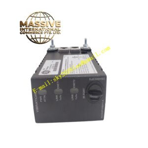
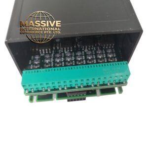
GE HE697RTM700B
Technical Specifications:
- Processor: Dual 32-bit RISC @ 266 MHz
- Memory: 512 MB RAM, 1 GB flash
- Redundancy: Triple modular redundancy (TMR) with 2oo3 voting
- Safety Rating: SIL 3 / SIL 4 per IEC 61508
- Scan Time: 20 ms (safety loop), 10 ms (control loop)
- Communication: Dual redundant Ethernet, Genius bus, serial
- Protocols: PROFIsafe, DeviceNet Safety, Modbus TCP
- Power: ~18 W
- Operating Temp: -20°C to +70°C (extended)
- MTBF: >500,000 hours (safety-rated)
Functional Features:
- Executes safety logic independently from the main CPU
- 2oo3 voting architecture eliminates single-point failures
- Built-in diagnostics with safe-state output on fault
- Event logging with 1 ms timestamp for post-trip analysis
- Supports online download of safety logic (with validation)
- Web-based configuration and diagnostic interface
Application Scenarios:
- Gas turbine overspeed trip (103% / 110% / 112% setpoints)
- Steam turbine emergency stop
- Generator loss-of-field protection
- Boiler flame failure protection
- Safety-critical ESD (Emergency Shutdown) systems
Material Composition:
- PCB: 10-layer with redundant trace routing for TMR
- Processor: Safety-certified component with self-test capability
- Memory: ECC-protected RAM and flash
- Enclosure: Hermetically sealed aluminum with conformal coating
- Connectors: Locking connectors to prevent accidental disconnection
Working Principle: Three identical processors execute the same safety logic in parallel. A voter circuit compares the three outputs and takes the majority result. If any processor disagrees, it is isolated and the remaining two continue operation (2oo3). All safety outputs are driven to a known safe state on any detected fault. Installation Requirements:
- Must be installed in a dedicated safety chassis or safety-rated slot
- Redundant power supplies required (dual 24 VDC)
- Safety I/O modules must be in the same safety chassis
- All safety wiring must be in dedicated safety-rated cable trays
Usage Precautions:
- Never modify safety logic without a formal change management process
- Perform proof test at recommended intervals (typically every 6–12 months)
- Maintain firmware version consistency across all three processors
- Do not use for non-safety functions — keep safety and control logic strictly separated