Description
GE IC200CHS022 Technical Specifications
-
Carrier Style: Compact box-style
-
Terminals: 36 IEC box-style terminals (A1–A18, B1–B18)
-
Dimensions: 66.8 mm (W) × 70 mm (D) × 167.89 mm (H) — 2.63 in × 2.75 in × 6.61 in
-
Weight: 0.75–0.91 kg (varies by source)
-
Voltage Rating: 0–264 VAC
-
Maximum Voltage per Point: 264 VAC
-
Transient Voltage: Up to 300 VAC
-
Current Rating: 2 A per point; 8 A per power/ground terminal
-
Wire Compatibility: Single wire: AWG #14 to #22 (0.36–2.1 mm²); Two-wire: AWG #18 (0.86 mm²)
-
Terminal Torque: 0.37–0.5 lbf·ft
-
Mounting: 35 mm DIN rail (7.5 mm × 35 mm) or panel mounting
-
Mounting Clearance: Top/bottom: 2 in (5.1 cm); Side: 1 in (2.54 cm)
-
Operating Temperature: 0°C to +60°C (32°F to 140°F)
-
Supply Voltage: 5 V DC (backplane)
Structural Features
-
I/O module mounts vertically (perpendicular to DIN rail)
-
Built-in card holder that hinges down over terminal wiring
-
Wiring card provided with I/O module inserts into holder
-
Card holder retracts during system operation
-
Easy-keying dials to match module keying and prevent misinstallation
-
Carrier-to-carrier mating connectors for quick backplane connection
-
Module latch hole for secure fastening
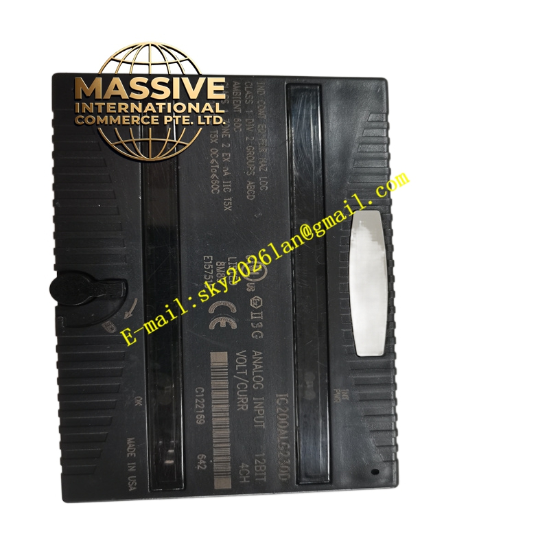
Hazardous Location Ratings Certified for Class I, Division 2, Groups A, B, C, D, and Class 1 Zone 2 locations.
Installation Requirements Snaps onto 7.5 mm × 35 mm DIN rail. The rail must be electrically grounded with a conductive, unpainted, corrosion-resistant finish for EMC protection. For applications requiring maximum vibration and shock resistance, panel-mount the carrier in addition to DIN rail mounting. One inch of horizontal spacing and two inches of vertical spacing should be provided around the mounted module.
Applications
-
Compact control panels with limited depth
-
Embedded control systems
-
Space-constrained machine control installations
-
Distributed I/O nodes in crowded electrical enclosures