Description
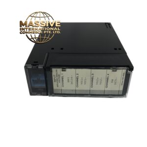
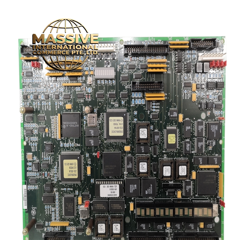
GE DS200LDCCH1ALA
- Technical Specifications:
- Channels: 2 independent load control channels (Channel A and Channel B)
- Inputs: Speed feedback (tachometer or encoder, 0–10,000 RPM); load feedback (4–20 mA from kW meter or current transformer)
- Outputs: 2 fuel solenoid control outputs (0–100% duty cycle PWM); 2 alarm relay outputs (dry contact, 2 A at 30 VDC)
- Speed Input Range: 0–10,000 RPM (AC or DC tachometer); 0–5,000 RPM (encoder)
- Load Input Range: 0–20 mA or 4–20 mA (proportional to kW or MVAR)
- Control Algorithm: PID with adaptive gain scheduling; droop control adjustable from 0% to 10%
- Load Sharing Accuracy: ±1% of rated load between parallel units
- Response Time: 100 ms from load change to 95% of new setpoint
- Isolation: 500 VDC channel-to-channel; 500 VDC channel-to-logic
- Power Supply: +5 VDC from backplane; 3.8 W typical power consumption
- Functional Features:
- Automatic Load Sharing: When multiple generators are paralleled, the LDCCH1ALA automatically adjusts each unit’s fuel solenoid to share the total load proportionally based on each unit’s capacity rating
- Load Shedding: Programmable load shed steps (up to 8 steps) that automatically disconnect non-essential loads when total demand exceeds available capacity
- Droop Control: Adjustable speed droop (0–10%) allows stable parallel operation without a master-slave configuration
- Engine Protection: Overspeed shutdown at 110% of rated speed; underspeed alarm at 90% of rated speed; low oil pressure shutdown input
- Synchronization: Built-in synchronizing relay control for generator breaker closure when voltage, frequency, and phase angle are within tolerance
- Black Start: Supports black start sequencing for emergency power restoration
- Application Scenarios:
- Diesel Generator Sets: Primary or standby power for hospitals, data centers, telecommunications towers, military installations
- Gas Engine Generators: Continuous power for industrial facilities, remote pipelines, mining operations
- Parallel Operation: Multiple generator sets sharing a common bus in power plants, commercial buildings, and industrial campuses
- Peak Shaving: Generator sets that run during peak utility demand periods to reduce electricity costs
- Emergency Power: Hospital and data center backup power with automatic transfer switch (ATS) integration
- Performance Parameters:
- Operating Temperature: 0°C to 60°C
- Storage Temperature: -40°C to 85°C
- Relative Humidity: 5% to 95% non-condensing
- MTBF: Greater than 160,000 hours
- EMC Compliance: IEC 61000-6-2, IEC 61000-6-4
- Material & Structure:
- Form Factor: Mark VI/VIe standard, approximately 180 mm × 120 mm × 15 mm
- Connectors: 2 × 20-pin field terminal blocks (speed, load, solenoid, alarm); 64-pin backplane connector
- PCB: 8-layer FR-4 with conformal coating and shielded sections around analog inputs
- Enclosure: Zinc-plated steel with EMI shielding can
- Weight: Approximately 420 grams
- Working Principle:
- The speed feedback signal is processed by a hardware frequency counter (as in the DCFBG board) and compared to the speed setpoint. The error is fed to a PID controller with adaptive gain that adjusts its proportional, integral, and derivative terms based on the magnitude of the error. The PID output drives a PWM generator that controls the fuel solenoid valve duty cycle (0% = closed, 100% = fully open). The load feedback signal is used by the load sharing algorithm to calculate each generator’s share of the total load. The droop control adds a speed offset proportional to the load, ensuring that when one generator picks up more load, its speed drops slightly, causing the other generators to pick up the difference. The synchronization function compares the generator voltage, frequency, and phase angle to the bus values and closes the breaker when all three are within programmed tolerance windows.
- Installation Requirements:
- Rack: Mark VI or Mark VIe I/O rack
- Speed Feedback: Connect tachometer or encoder to the speed input terminal block; use shielded twisted-pair cable
- Load Feedback: Connect 4–20 mA signal from the kW meter or CT to the load input; ensure the signal is properly scaled (e.g., 4 mA = 0 kW, 20 mA = rated kW)
- Fuel Solenoid: The board outputs a PWM signal; connect to the engine’s electronic fuel actuator (EFA) or fuel solenoid valve as specified by the engine manufacturer
- Alarm Relays: Dry contact outputs rated 2 A at 30 VDC; connect to engine shutdown solenoids or alarm annunciators
- Usage Notes:
- Droop Setting: For stable parallel operation, set all generators to the same droop percentage (typically 4–5%); the master generator should have droop set to 0% (isochronous mode)
- Load Shed Steps: Program load shed steps in descending order of priority (e.g., step 1 = HVAC, step 2 = lighting, step 3 = non-critical process loads)
- Synchronization Tolerance: Typical settings are ±0.5 Hz for frequency, ±5° for phase angle, and ±10% for voltage; adjust based on generator and breaker manufacturer specifications
- Black Start Sequence: Configure the black start relay outputs to close in the correct sequence (e.g., start generator 1, wait 30 seconds, close breaker 1, start generator 2, wait 30 seconds, close breaker 2)
- Calibration: Calibrate the load input channel using a precision mA source; verify the kW reading at 0%, 50%, and 100% of rated load