Description
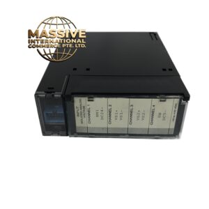
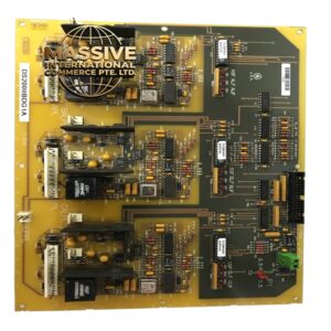
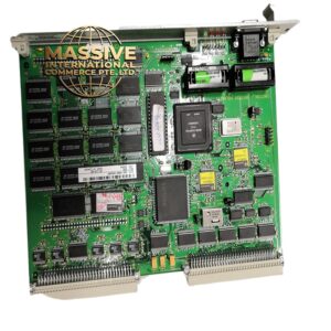
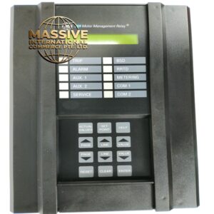
GE CE4002S1T2B5
Technical Specifications:
- Primary Current Rating: 400A (typical for CE4002-400)
- Secondary Current Rating: 5A (standard) or 1A (optional)
- Accuracy Class (Metering): 0.5S (IEC 61869-2)
- Accuracy Class (Protection): 5P20 (5% error at 20x rated current)
- Rated Burden: 5VA at 5A secondary
- Rated Frequency: 50Hz / 60Hz
- Insulation Level: 3kV RMS / 50Hz / 1 minute (primary to secondary)
- Impulse Withstand Voltage: 15kV peak (1.2/50μs wave)
- Short-Time Thermal Current: 80kA for 1 second (typical)
- Dynamic Current: 200kA peak (typical)
- Core Material: Grain-oriented silicon steel (M6 grade, 0.23mm lamination)
- Window Type: Bushing type (for cable passing) or window type
- Window Diameter: 80mm to 120mm (depending on variant)
- Overall Dimensions: Approximately 180mm x 140mm x 100mm (H x W x D)
- Weight: Approximately 4.5kg to 6kg
- Standards: IEC 61869-2, IEEE C57.13, ANSI C57.13, UL listed
Functional Features:
- Dual accuracy class (0.5S metering + 5P protection) allows one CT to serve both energy meter and protection relay
- Low phase angle error (less than 15 minutes at rated burden) ensures accurate kWh metering
- Epoxy resin encapsulation provides moisture resistance and mechanical protection
- Short-time thermal withstand rating ensures CT survives fault currents without damage
- Built-in shorting link on secondary terminals for safe maintenance
- Flame-retardant housing meets IEC 60695 fire safety requirements
Application Scenarios:
- Medium voltage switchgear (3.3kV to 36kV) in commercial buildings
- Energy metering panels for utility billing (0.5S accuracy required)
- Motor protection circuits in industrial facilities
- Generator protection in power plants
- Renewable energy (solar/wind) inverter input monitoring
- Data center main feeder metering
Performance Parameters:
- Ratio Error at 100%: Less than 0.5% (metering), less than 5% (protection)
- Phase Displacement at 100%: Less than 15 minutes (metering), less than 120 minutes (protection)
- Composite Error at 20x Rated Current: Less than 5% (5P class)
- Knee Point Voltage: Greater than 400V (typical for 5P class)
- Excitation Current at Rated Voltage: Less than 50mA
- Thermal Rating Factor: 1.0 (continuous operation at rated current)
Material Composition:
- Core: Grain-oriented silicon steel (M6, 0.23mm thickness)
- Windings: Copper (99.9% purity, Class 1) with polyester film insulation
- Housing: Epoxy resin cast (self-extinguishing, UL94 V-0)
- Terminals: Brass with tin plating
- Shorting Link: Copper with spring-loaded mechanism
Structure Features:
- Bushing-type design allows the primary conductor (cable or busbar) to pass through the CT window
- Secondary terminals are located on the top for easy access
- Shorting link is clearly marked and color-coded (red = shorted, green = open)
- Nameplate shows all ratings, accuracy class, and wiring diagram
- IP20 protection rating (indoor use only)
Working Principle: The primary current flowing through the conductor creates a magnetic flux in the silicon steel core. This flux induces a proportional secondary current in the copper windings according to the turns ratio (e.g., 400:5 = 80:1). The 0.5S accuracy class ensures that at normal load currents (20% to 120% of rated), the ratio error and phase displacement are within tight limits for accurate energy measurement. The 5P class ensures that during fault conditions (up to 20x rated current), the CT does not saturate excessively, allowing the protection relay to operate correctly. Installation Requirements:
- Pass the primary conductor through the CT window (direction marked with arrow on housing)
- Connect secondary wires to S1 and S2 terminals (polarity must be observed: P1/P2 for primary, S1/S2 for secondary)
- Always short the secondary terminals (using the built-in link) before disconnecting any wire
- Connect the secondary circuit to the meter or relay using 2.5mm² copper wire maximum length 10m
- Ground one point of the secondary circuit (typically S2) to the panel ground bar
Usage Notes:
- Never leave the secondary circuit open while primary current is flowing (dangerous high voltage will appear)
- Verify CT ratio matches the meter/relay setting before energizing
- Do not exceed the rated burden (5VA) or accuracy will degrade
- Perform ratio and polarity test during commissioning