Description
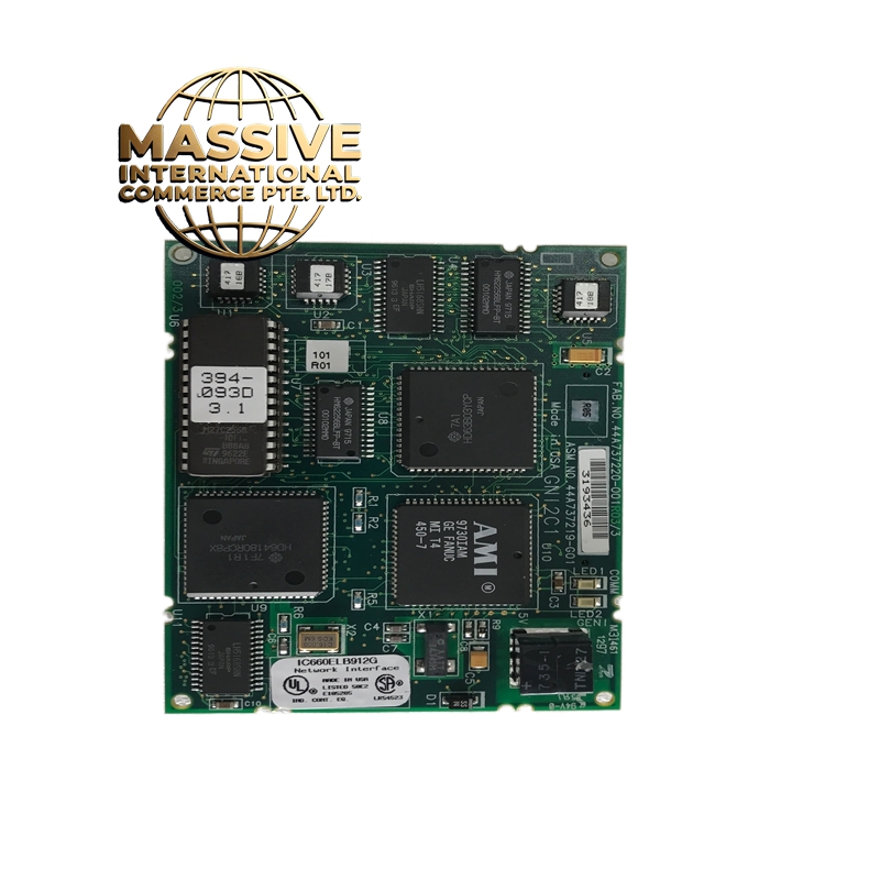
GE IC660ELB912G
- Technical Specifications:
- Channels: 12 independent digital input channels
- Input Type: 24VDC sourcing (PNP)
- Input Voltage Range: 18VDC to 30VDC (logic high), 0V to 5VDC (logic low)
- On/Off Threshold: 10VDC typical turn-on, 3VDC typical turn-off
- Input Current: Approximately 3.5mA per channel (sourcing)
- Response Time: 1ms ON to OFF, 10ms OFF to ON (typical)
- Isolation: Optically isolated, 500V RMS
- Power Consumption: Approximately 3W total
- Operating Temperature: 0°C to 60°C
- Functional Features:
- 12 independent input points with individual LED status indicators
- Supports sourcing (PNP) sensor type — common in European/Asian sensor standards
- Backplane-powered — no external power supply needed for the module itself
- Diagnostic LEDs per channel for troubleshooting
- Compatible with GE Proficy Machine Edition programming software
- Application Scenarios:
- Detecting presence/absence of parts on assembly lines
- Limit switch monitoring on CNC machines
- Safety door interlock status reading
- Conveyor object detection
- Valve position feedback
- Performance Parameters:
- Input Impedance: Approximately 7kΩ (typical)
- Optical Isolation: 500V RMS between field and logic side
- Bus Communication Speed: VersaMax high-speed backplane, 10Mbps
- MTBF: Greater than 200,000 hours
- Material Composition:
- Housing: UL94 V-0 flame-retardant polycarbonate/ABS blend
- PCB: Multi-layer FR-4 with conformal coating
- Connectors: Gold-plated backplane edge connector, screw-terminal field connectors
- LEDs: High-brightness red LEDs for status indication
- Structural Features:
- Standard IC660 form factor, DIN-rail mountable
- 12 individual green LED indicators (one per channel) on the front panel
- Screw-type terminal blocks for field wiring (18-26 AWG)
- Keying notch on PCB for correct orientation in rack
- Working Principle:
- When a 24VDC sourcing sensor activates, it provides +24V to the input terminal. The module detects this voltage through an internal opto-isolator. The opto-coupler’s phototransistor conducts, pulling the logic side low, which the PLC CPU reads as a logic “1”. When no signal is present, the input is pulled low internally, read as logic “0”.
- Installation Requirements:
- Install in VersaMax I/O chassis (IC695CHS or IC697 chassis)
- Use 18-26 AWG stranded or solid wire for field connections
- Ensure sensor ground is common with PLC ground
- Maintain adequate spacing for heat dissipation
- Usage Precautions:
- Only connect PNP (sourcing) sensors — connecting NPN sensors will not work correctly
- Do not apply voltage exceeding 30VDC to any input channel
- Use shielded cable in high-EMI environments
- Verify wiring polarity — reversing +24V and 0V will not damage but will give inverted logic
- Do not exceed 12 channels of simultaneous switching at maximum frequency