Description
GE IC676PBO082
- Technical Specifications:
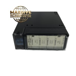
- Channels: 8 independent relay output channels
- Output Type: Mechanical relay, SPDT (Single Pole Double Throw)
- Contact Rating: 2A at 250VAC, 2A at 30VDC (resistive load)
- Coil Voltage: 24VDC (internal)
- Switching Time: 10ms typical (energize to contact change)
- Mechanical Life: 10,000,000 operations
- Electrical Life: 100,000 operations at full rated load
- Isolation: 500V RMS between channels and to logic bus
- Power Consumption: Approximately 8W total (coil power for all 8 relays)
- Operating Temperature: 0°C to 60°C (32°F to 140°F)
- Storage Temperature: -40°C to 85°C
- Humidity: 5% to 95% non-condensing
- Dimensions: Standard IC676 module form factor (approximately 165mm x 98mm x 120mm)
- Functional Features:
- 8 SPDT relays with Normally Open (NO) and Normally Closed (NC) contacts per channel
- Each channel has an individual LED status indicator on the front panel
- Backplane-powered — no external power supply required for the module itself
- Optical isolation per channel group for noise immunity
- RC snubber network across each relay contact for inductive load protection
- Compatible with GE Proficy Machine Edition and CIMPLICITY programming software
- Hot-swap capable in supported chassis configurations
- Application Scenarios:
- Local I/O expansion on compact 90-70 CPU installations
- Small machine control panels requiring 8 discrete outputs
- Solenoid valve actuation in fluid control systems
- Indicator light and alarm horn control
- Auxiliary equipment start/stop control
- Legacy equipment interfacing where relay isolation is required
- Panel-mounted distribution of outputs from a central CPU
- Performance Parameters:
- Contact Resistance: Less than 100 milliohms initial
- Dielectric Strength: 1500V RMS for 1 minute between contacts
- Coil Current: Approximately 80mA per channel at 24VDC
- Common Mode Rejection: Greater than 1000V
- Bus Communication: Genius Bus / VersaMax backplane, 10Mbps data rate
- MTBF: Greater than 200,000 hours
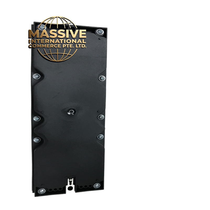
- Material Composition:
- Housing: Flame-retardant ABS plastic, UL94 V-0 rated
- PCB: 4-layer FR-4 glass epoxy, conformally coated for moisture protection
- Relays: Sealed electromagnetic relays with silver alloy contacts
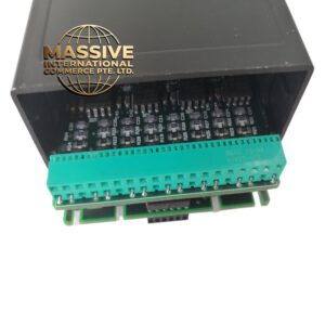
- Connectors: Gold-plated backplane edge connector for processor base
- Terminals: Screw-type terminal blocks, 18 to 22 AWG wire compatible
- LEDs: High-brightness red LEDs for channel status indication
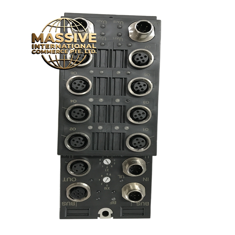
- Structural Features:
- Standard IC676 module width and height
- 8 individual red LED indicators on the front panel
- Processor base connector with keying for correct orientation
- Screw-terminal field connections for each relay output (NO, COM, NC)
- DIN-rail mountable or processor base mountable
- Keyed slot on PCB for alignment in base unit
- Working Principle:
- The PLC CPU writes to the output register via the backplane bus. The module receives the digital value and energizes the corresponding relay coil internally. When the coil is energized, the mechanical contacts switch from the Normally Closed (NC) position to the Normally Open (NO) position. The front-panel LED illuminates to indicate the relay is active. The RC snubber network suppresses voltage spikes generated when the relay de-energizes, protecting the contact surfaces from arcing damage. The optical isolation barrier prevents electrical noise from the field side from reaching the CPU logic.
- Installation Requirements:
- Mount directly onto a GE 90-70 CPU or compatible processor base unit
- Ensure the module is fully seated in the base connector before powering up
- Use 18 to 22 AWG stranded or solid wire for field connections
- Connect each load between the COM terminal and either NO or NC terminal
- For inductive loads (solenoids, relay coils), verify the internal snubber is adequate or add an external suppression diode
- Maintain at least 10mm clearance between modules for airflow
- Ground the module chassis to the panel ground bus
- Usage Precautions:
- Do not exceed 2A per channel — use an external contactor or relay for higher current loads
- Do not switch loads at maximum frequency — mechanical relays have finite life
- Verify the load voltage matches the relay contact rating (AC or DC)
- Do not mix AC and DC loads on the same channel
- Add external flyback diodes for DC solenoid loads if the internal snubber is insufficient
- Do not hot-swap unless the chassis explicitly supports hot-swap operation
- Keep output wiring separated from high-current power cables by at least 30cm