Description
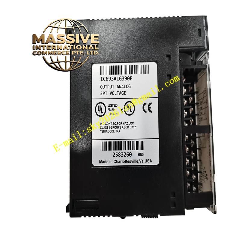
GE IC693ALG390 Technical Specifications:
- Output Channels: Multiple isolated analog output channels.
- Signal Types: Configurable voltage or current outputs.
- Resolution: High-resolution digital-to-analog conversion.
- Update Rate: Fast output refresh rate for smooth control.
Functional Features:
- Precise Control: Accurate signal generation for tight process control.
- Isolation: Galvanic isolation between outputs and backplane.
- Fail-Safe: Configurable output states (hold last, go to zero, go to full scale) upon CPU fault.
- Diagnostics: Short circuit and open loop detection.
Application Scenarios:
- Closed-loop PID control for temperature, pressure, and flow.
- Speed control of motors and pumps via VFDs.
- Positioning control for actuators and dampers.
Performance Parameters:
- Linearity: Excellent linearity across the full output range.
- Ripple: Low output ripple for smooth actuator movement.
- Response Time: Rapid response to setpoint changes.
Material Composition & Structural Characteristics:
- Circuitry: Precision DACs and operational amplifiers.
- Protection: Output short-circuit and overvoltage protection.
- Connectors: Secure terminal blocks with clear labeling.
Working Principle: The PLC CPU writes digital values to the module’s output registers. The module’s DAC converts these values to analog voltages or currents. Internal amplifiers buffer and condition the signals before delivering them to the field devices. If a fault is detected, the module executes the pre-configured fail-safe state.
Installation Requirements:
- Wiring: Use shielded cables and observe proper grounding practices.
- Load Impedance: Ensure the connected load impedance is within the module’s specified range.
- Power: Verify adequate power supply capacity for the module and connected loads.
Usage Precautions:
- Short Circuits: Do not short-circuit output terminals; the module has protection, but sustained shorts can cause damage.
- Inductive Loads: Use flyback diodes or snubbers when driving inductive loads.
- Configuration: Double-check fail-safe settings before commissioning to ensure safe process behavior during faults.