Description
GE IC693CHS398
- Technical Specifications:
- Channels: 4 independent high-speed counter channels
- Input Type: 5V differential (RS-422 compatible, A/B phase per channel)
- Maximum Frequency: 5MHz per channel
- Counter Resolution: 32-bit signed (−2,147,483,648 to +2,147,483,647)
- Input Voltage: 5V differential nominal
- Input Impedance: 100 ohms differential per channel
- Isolation: 500V RMS optical isolation from backplane (per channel group)
- Power Consumption: Approximately 2.5W
- Operating Temperature: 0°C to 60°C
- Dimensions: Standard IC693 module form factor (full width)
- Functional Features:
- 4 independent 32-bit counters with quadrature decoding (A/B phase) per channel
- Each channel supports up/down counting, modulo counting, latch, and capture
- Hardware-based counting — completely independent of CPU scan cycle
- Z (index) pulse input per channel for home position reference
- Diagnostic LED per channel (4 LEDs total)
- Backplane-powered
- Compatible with GE CIMPLICITY and Logicmaster 90-30
- Two isolation groups: channels 1-2 and channels 3-4
- Application Scenarios:
- Multi-axis servo motor control (4 axes simultaneously)
- CNC machine with 4-axis encoder feedback
- Multi-conveyor position tracking system
- Robotic arm joint position monitoring
- Printing press multi-color register control
- Packaging machine with multiple encoder inputs
- Performance Parameters:
- Counting Accuracy: Plus or minus 1 count at 5MHz
- Response Time: Less than 500 nanoseconds per count
- Common Mode Rejection: Greater than 1000V per channel
- Noise Immunity: RS-422 differential signaling
- Bus Speed: Genius Bus, 10Mbps
- MTBF: Greater than 200,000 hours
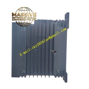
- Material Composition:
- Housing: UL94 V-0 polycarbonate
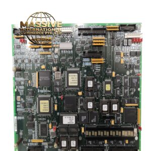
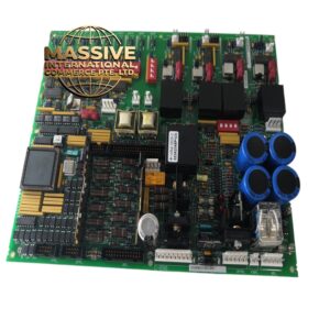
- PCB: 4-layer FR-4, conformally coated
- Connectors: Gold-plated backplane edge connector, screw terminals for all 4 encoder sets
- Isolation: High-speed opto-isolators per channel group
- LEDs: 4 green status indicators on front panel
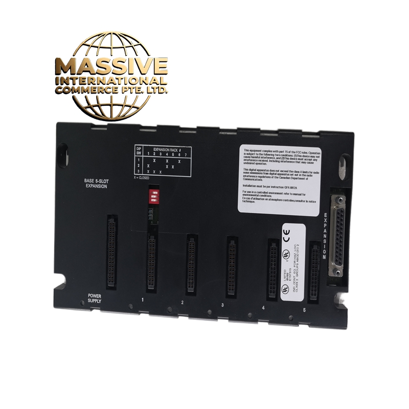
- Structural Features:
- Full-width IC693 module
- 4 green LED indicators (one per channel)
- Screw-terminal connections for each encoder’s A+, A−, B+, B−, Z+, Z− signals
- DIN-rail or chassis mountable
- Keying notch for correct orientation
- Two isolation barrier zones on PCB (channels 1-2 and 3-4)
- Working Principle:
- Each of the 4 channels independently receives differential A/B phase encoder signals. Internal FPGA hardware decodes the quadrature signals, determines direction, and accumulates counts in a 32-bit register per channel. The Z pulse provides a once-per-revolution index for homing. The CPU reads all 4 counter values via the Genius Bus. Because counting is hardware-based, no counts are lost regardless of CPU scan cycle timing. Optical isolation protects each channel group from electrical noise.
- Installation Requirements:
- Mount in IC693 or IC695 chassis
- Use shielded twisted-pair cable (120 ohm impedance) for each encoder
- Connect A+, A−, B+, B−, Z+, Z− for each encoder to the corresponding terminals
- Ground all cable shields at the chassis end only (single-point grounding)
- Keep encoder cables at least 30cm away from high-power motor drives and AC power cables
- Add 100 ohm termination resistors across A+/A− and B+/B− if cable length exceeds 10 meters
- Usage Precautions:
- Do not exceed 5V differential on any input — this will damage the module
- Do not connect single-ended encoder outputs to differential inputs without a signal converter
- Verify all encoders output RS-422 level signals (5V differential)
- Use proper cable termination for runs longer than 10 meters
- Do not hot-swap — power down the chassis before inserting or removing
- Ensure the CPU has sufficient scan time to read all 4 counters if using software-based position calculations
- In multi-axis applications, synchronize the counters using the Z pulse for consistent position reference across all axes