Description
GE IC697ACC720 Technical Specifications:
- Signal Resolution: High-resolution 16-bit Analog-to-Digital (A/D) conversion.
- Signal Types: Supports multiple analog inputs and outputs, including voltage (e.g., 0-10V) and current (e.g., 4-20mA).
- Processing Speed: Fast processing cycle supporting high-speed real-time control.
- Isolation: Comprehensive electrical isolation between input/output channels and the system backplane.
- Form Factor: Compact modular design for high-density rack installation.
Functional Features:
- Advanced Signal Conditioning: Built-in filtering, scaling, and offset adjustments to clean noisy field signals.
- Per-Channel Diagnostics: Real-time monitoring of each channel for open wires, short circuits, and out-of-range conditions.
- Flexible Configuration: Software-selectable parameters allow each channel to be independently configured for different signal types.
- Alarm Generation: Configurable high/low limits and rate-of-change alarms for proactive process monitoring.
Application Scenarios:
- Precision temperature and pressure control in chemical processing.
- Flow rate monitoring and regulation in water treatment facilities.
- Position and speed feedback in manufacturing automation.
- Power monitoring and load balancing in energy systems.
Performance Parameters:
- Accuracy: High-precision conversion with minimal drift over temperature variations.
- Scan Time: Fast update rates to ensure responsive control loops.
- Noise Rejection: Excellent common-mode and normal-mode noise rejection due to robust isolation and filtering.
Material Composition & Structural Characteristics:
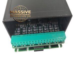
- Terminal Block: High-quality, secure接线端子 (wiring terminals) designed for reliable connections and easy maintenance.
- PCB Assembly: Industrial-grade components with conformal coating to protect against moisture and corrosive gases.
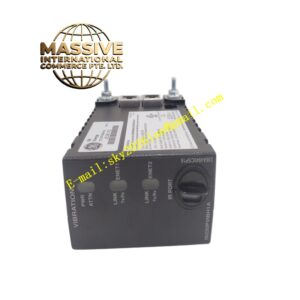
- Status Indicators: Front-panel LEDs for module health, channel status, and fault indication.
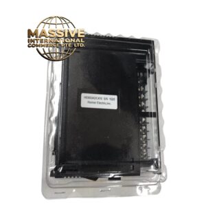
- Housing: Durable plastic enclosure designed for DIN rail or rack mounting.
Working Principle: For inputs, the module receives low-level analog signals from field sensors, conditions them through amplifiers and anti-aliasing filters, and converts them to 16-bit digital values using precision A/D converters. For outputs, it receives digital values from the CPU and converts them back to analog signals using Digital-to-Analog (D/A) converters to drive actuators. The microcontroller manages scaling, diagnostics, and backplane communication.
Installation Requirements:
- Wiring: Use shielded twisted-pair cables for all analog signals to minimize electromagnetic interference.
- Grounding: Connect cable shields at the module end only to prevent ground loops.
- Slot Assignment: Install the module in a designated analog I/O slot in the PLC rack.
- Software Configuration: Define signal types, scaling factors, and alarm limits in the PLC programming software.
Usage Precautions:
- Signal Limits: Never apply voltages or currents exceeding the module’s maximum ratings to prevent permanent damage.
- Calibration: Perform periodic calibration checks using precision signal generators to maintain measurement accuracy.
- ESD Protection: Always use electrostatic discharge precautions when handling or installing the module.
- Diagnostics: Utilize the PLC’s diagnostic tools to quickly identify and resolve channel-specific faults.