Description
GE IC697MDL750E
- Technical Specifications:
- Channels: 16 independent relay output channels
- Output Type: Electromechanical relay (Form C / SPDT)
- Contact Rating: 2A @ 250VAC or 2A @ 30VDC (resistive load)
- Coil Voltage: 24VDC
- Coil Current: 80mA per channel (typical)
- Switching Time: 8ms typical (energize), 5ms typical (de-energize)
- Mechanical Life: 10,000,000 operations
- Electrical Life: 100,000 operations at full load
- Isolation: 500V RMS between channels, 500V RMS to backplane
- Power Consumption: ~1.5W (coil power, all channels off), ~12.8W (all channels on)
- Operating Temperature: 0°C to 60°C
- Dimensions: Standard IC697 module form factor (wider than standard due to 16 channels)
- Functional Features:
- 16 SPDT relay outputs — NO, NC, COM per channel
- LED indicator per channel for output status
- Backplane-powered — no external power supply needed
- Snubber circuit (RC network) across each relay contact for inductive load protection
- Two isolation groups (channels 1-8 and 9-16) for mixed-voltage safety
- Compatible with 90-70 CPUs and Proficy Machine Edition
- Application Scenarios:
- High-channel-count output switching in process plants
- Motor starter control (small motors via contactor relay)
- Solenoid valve actuation (pneumatic/hydraulic)
- Alarm and indicator light control
- Mixed AC/DC load switching (relay contacts are voltage-agnostic)
- Legacy equipment interfacing where relay isolation is required
- Performance Parameters:
- Contact Resistance: <100mΩ (initial), <200mΩ (end of life)
- Dielectric Strength: 1500V RMS for 1 minute between contacts
- Coil Insulation: 1500V RMS
- Common Mode Rejection: >1000V
- Bus Interface: Genius Bus (90-70)
- Material Composition:
- Housing: UL94 V-0 polycarbonate/ABS blend
- Relays: Sealed electromagnetic relays with silver-nickel alloy contacts
- PCB: 4-layer FR-4, conformal coated
- Snubber: RC network (100Ω + 0.1μF) per relay contact
- Terminals: Screw-type, 18-22 AWG, tin-plated copper
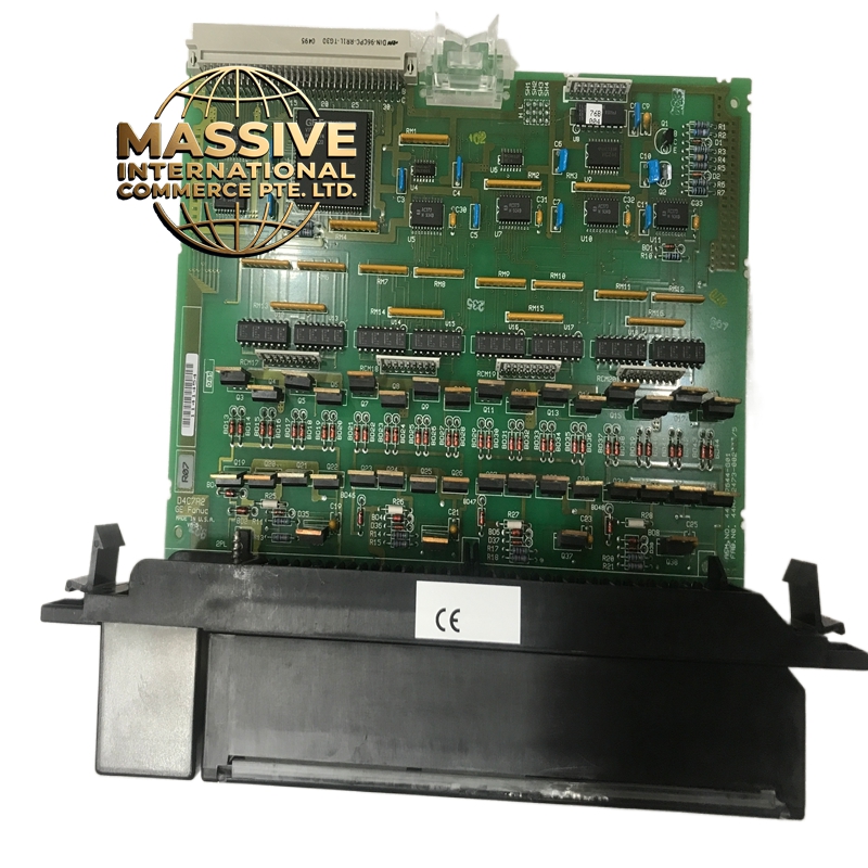
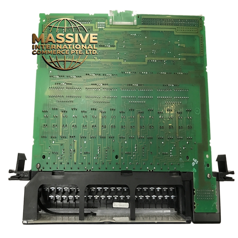
- Structural Features:
- Wide IC697 module (approximately 2x standard width for 16 channels)
- 16 LED indicators (red) on front panel
- Screw terminals per channel: NO, COM, NC
- Two isolation barrier zones visible on PCB
- DIN-rail mountable
- Working Principle:
- The CPU writes to the output register via the Genius Bus backplane. The module’s internal logic energizes the relay coil for the selected channel. The electromagnetic relay mechanically switches the contact from NC to NO. The LED indicates when the relay is energized. The mechanical nature provides galvanic isolation (no electrical connection) between the PLC logic and the load circuit.
- Installation Requirements:
- Mount in IC697 chassis (90-70 compatible)
- Wire loads to COM and NO (or NC) terminals per channel
- For inductive loads (solenoids, relay coils), use external flyback diode or ensure snubber is active
- Use 18-22 AWG wire for field connections
- Connect common ground to PLC chassis ground
- Usage Precautions:
- Do not exceed 2A per channel — use external contactor for larger loads
- Do not switch at maximum frequency — mechanical relays wear out
- Add external suppression for highly inductive loads (large solenoids, motor coils)
- Verify AC/DC rating matches your load voltage and current
- Allow 8ms delay in logic for relay switching time
- Do not mix AC and DC loads on the same channel — use separate channels