Description
GE IS200JPDFG1A Technical Specifications:
- System Compatibility: GE Mark VI Speedtronic Control System.
- Power Distribution: Distributes DC power to high-capacity DC buses and DACA modules.
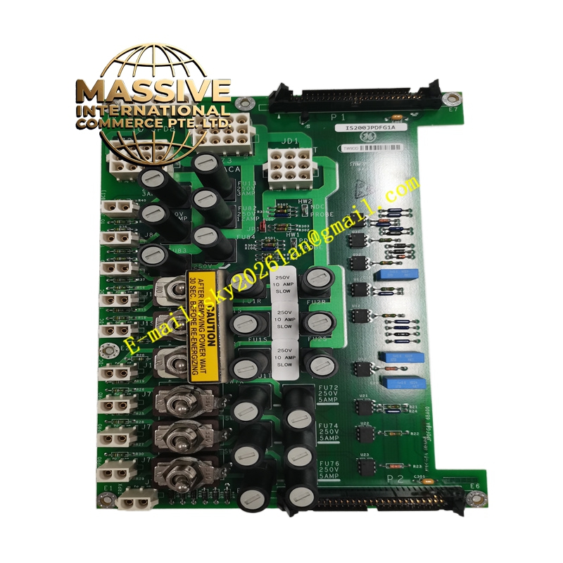
- Protection: Equipped with 18 independent fuses for overcurrent protection.
- Connectors: Features 14 plug connectors, including 2-position (10 units), 12-position (2 units), 9-position, and 5-position plugs.
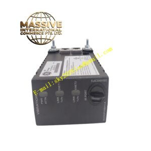
- Switches: Six toggle switches aligned in a single row, with three featuring a safety warning label.
Functional Features:
- System Feedback: Utilizes ribbon cable connections to provide system feedback, including DC bus voltage monitoring and ground fault detection via the PPDA board.
- Power Management: Safely distributes and manages DC power across multiple control modules.
- Safety Interlocks: Integrated warning labels and switch configurations to prevent accidental power cycling.
- Fault Isolation: Individual fusing isolates faults to specific circuits, preventing system-wide failures.
Application Scenarios:
- Heavy-duty gas and steam turbine management.
- Power generation plants utilizing GE Speedtronic Mark VI systems.
- Petrochemical and metallurgical industrial processes requiring precise turbine control.
Performance Parameters:
- Safety Delay: Requires a mandatory 30-second wait time after power-off before re-energizing to allow capacitor discharge.
- Reliability: High-density fuse protection ensures continuous operation under fault conditions.
- Feedback Accuracy: Real-time monitoring of DC bus voltage and ground fault status.
Material Composition & Structural Characteristics:
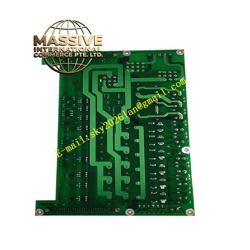
- Board Assembly: Multi-layer printed circuit board (PCB) with high-density surface-mount components.
- Protection Components: 18 independent fuses and 6 toggle switches for localized control.
- Connectors: 14 industrial-grade plug connectors for secure and reliable field wiring.
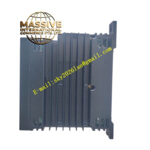
- Enclosure: Designed to integrate seamlessly into the Mark VI control rack.
Working Principle: The IS200JPDFG1A receives raw DC power and routes it through protected circuits to various downstream modules. The onboard fuses protect each circuit from overcurrent conditions. Ribbon cables transmit real-time voltage and ground fault data back to the main controller, enabling predictive maintenance and immediate fault response.
Installation Requirements:
- Power Off: Always ensure the system is completely powered down and wait at least 30 seconds before installation or maintenance.
- Wiring: Connect the appropriate DC power sources and distribution cables to the designated plug connectors.
- Fuse Verification: Ensure all 18 fuses are intact and properly seated before energizing the system.
- Ribbon Cables: Securely connect the ribbon cables to the PPDA board for feedback functionality.
Usage Precautions:
- Capacitor Discharge: Strictly adhere to the 30-second wait time after power-off to avoid electrical shock.
- Fuse Replacement: Only replace blown fuses with identical specifications to maintain circuit protection integrity.
- Ground Fault Monitoring: Continuously monitor ground fault indicators to prevent insulation degradation and system damage.
- ESD Protection: Use proper electrostatic discharge (ESD) precautions when handling the board.