Description
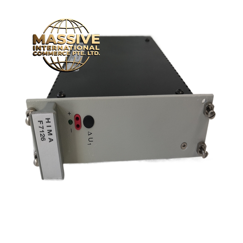
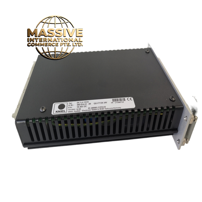
GE F7126
- Technical Specifications:
- Interface: Fiber optic (multimode, 62.5/125 μm) with ST connectors
- Fiber Distance: Up to 1000 meters (multimode); up to 10 km (single-mode with optional transceiver)
- Data Rate: 5 Mbps (sufficient for up to 256 I/O points per remote rack)
- Protocol: GE Fanuc Genius Bus protocol over fiber
- I/O Capacity: Supports up to 4 remote I/O racks, each with up to 64 I/O points (total 256 points)
- Digital I/O: 24 VDC, 16 channels per remote rack (sinking or sourcing)
- Analog I/O: 4–20 mA or 0–10 VDC, 8 channels per remote rack
- Isolation: 500 fiber optic isolation (galvanic isolation between CPU rack and remote racks)
- Power Supply: +5 VDC from Series 90-70 backplane; remote racks powered locally (24 VDC)
- Power Consumption: 1.8 W typical
- MTBF: Greater than 120,000 hours
- Diagnostics: Fiber link status LED (green = link OK, red = link fault); per-rack communication status LED
- Functional Features:
- Fiber Optic Isolation: Complete galvanic isolation between the CPU rack and remote racks eliminates ground loops and protects the CPU from field-side electrical transients
- Hot Swap: Fiber optic cables can be disconnected and reconnected without powering down the system (the module detects link loss and resumes automatically)
- Auto-Discovery: The module automatically detects connected remote racks and configures their I/O points; no manual addressing required
- Redundant Fiber: Supports dual fiber optic paths for redundant communication; automatic failover if the primary fiber is cut
- Diagnostic Reporting: The module reports per-rack status (communication OK, I/O fault, power fault) to the Series 90-70 CPU via the backplane bus
- Expandable: Up to 4 remote racks can be connected to a single F7126 module; additional modules can be added for more remote racks
- Application Scenarios:
- Power Plants: Remote I/O for boiler feedwater pumps, condenser cooling water valves, and air heater fans located far from the main control room
- Oil & Gas: Remote I/O for wellhead valves, pipeline SCADA RTUs, and compressor station controls located in remote field areas
- Water/Wastewater: Remote I/O for pump stations, valve chambers, and chemical dosing skids spread across a large facility
- Manufacturing: Distributed I/O for conveyor systems, packaging lines, and material handling equipment spread across a large factory floor
- Mining: Remote I/O for conveyor belts, hoists, and ventilation fans located deep underground or at remote surface locations
- Performance Parameters:
- Operating Temperature: 0°C to 60°C
- Storage Temperature: -40°C to 85°C
- Relative Humidity: 5% to 95% non-condensing
- EMC Compliance: IEC 61000-6-2, IEC 61000-6-4
- Shock: 15 g, 11 ms half-sine
- Vibration: 1 g, 10–500 Hz
- Material & Structure:
- Form Factor: Series 90-70 standard module, approximately 160 mm × 100 mm × 20 mm (Eurocard)
- Connectors: 2 × ST fiber optic connectors (primary and redundant); 96-pin DIN 41612 Eurocard backplane connector
- PCB: 6-layer FR-4 with conformal coating
- Enclosure: Anodized aluminum alloy (6061-T6) with steel mounting bracket
- Weight: Approximately 280 grams
- Front Panel: 2 green LEDs (primary fiber link, redundant fiber link); 1 amber LED (fault); 1 green LED (power)
- Working Principle:
- The Series 90-70 CPU sends I/O data to the F7126 via the VMEbus backplane. The ‘s onboard processor packages the data into Genius Bus frames and transmits them over the fiber optic link using an LED transmitter (850 nm wavelength for multimode fiber). At the remote end, a Genius Bus fiber optic receiver module (installed in the remote rack) converts the optical signal back to electrical Genius Bus signals and distributes them to the remote I/O modules. The reverse path carries remote I/O status back to the CPU. The fiber optic link provides complete galvanic isolation because there is no electrical connection between the two ends; data is transmitted as light pulses.
- Installation Requirements:
- Rack: Series 90-70 CPU rack; install in any standard VME slot
- Fiber Optic Cable: Use multimode 62.5/125 μm fiber optic cable with ST connectors; do not exceed 1000 meters for multimode; use single-mode fiber for distances over 1000 meters (requires optional single-mode transceiver)
- Remote Rack Power: Remote racks must be powered by a local 24 VDC power supply; the F7126 does not provide power to remote racks
- Fiber Routing: Avoid bending the fiber optic cable tighter than 30 mm radius; use fiber optic cable trays with proper bend radius support
- Redundant Fiber: Route the redundant fiber along a different physical path from the primary fiber to protect against a single point of failure (e.g., backhoe cut)
- Usage Notes:
- Do not look directly into the fiber optic connector; the 850 nm laser can cause eye damage
- Fiber Cleaning: Clean fiber optic connectors with a lint-free wipe and isopropyl alcohol before mating; dirty connectors are the number one cause of link failures
- Link Loss: If the fiber link is lost, the module will attempt to re-establish the link every 5 seconds; if the link is not restored within 30 seconds, the remote I/O points will be set to their fail-safe state (configurable per point)
- Maximum Distance: For multimode fiber, do not exceed 1000 meters; for single-mode fiber, do not exceed 10 km (with single-mode transceiver)
- Configuration: Use the Series 90-70 Programming Software to configure the F7126; specify the number of remote racks, the I/O point count per rack, and the fiber optic path (primary/redundant)
- Replacement: The F7126 is pin-compatible with other Series 90-70 VME modules; it can be hot-swapped in a redundant system without disrupting operation