Description
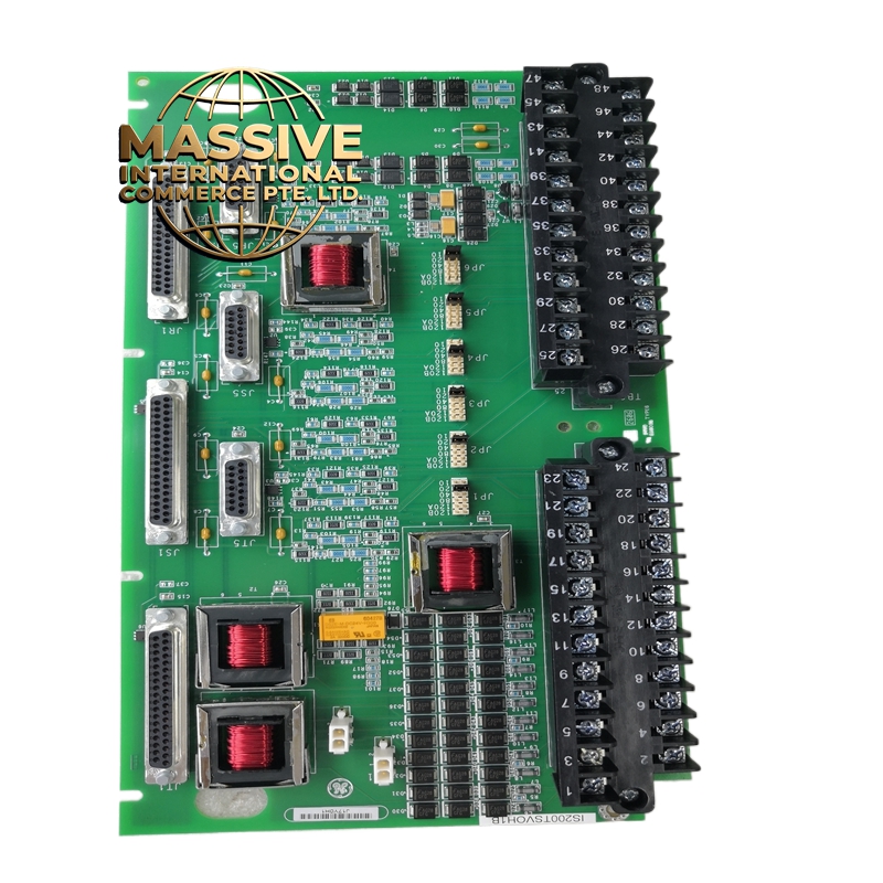
GE IS200TSVOH1B
Technical Specifications
| Parameter | Specification |
|---|---|
| Function | Servo Valve Signal Distribution |
| System Compatibility | Mark VI Speedtronic |
| Input Channels | Multiple servo valve drive signals |
| Output Configuration | Direct connection to servo valve coils |
| Signal Type | Analog servo current outputs |
| Board Dimensions | Standard Mark VI form factor |
| Operating Temperature | 0°C to 60°C (32°F to 140°F) |
| Storage Temperature | -40°C to 85°C (-40°F to 185°F) |
| Humidity | 5% to 95% non-condensing |
| Power Requirements | Powered from system backplane |
Functional Features
-
Signal Distribution: Routes servo valve drive signals from the VME processor board to external servo valves
-
Current Loop Interface: Provides proper current loop termination for servo valve coils
-
Diagnostic Feedback: Includes feedback paths for servo valve position monitoring
-
Protection Circuitry: Incorporates overcurrent and transient protection for connected servo valves
-
Modular Design: Hot-swappable design for maintenance without system shutdown
Structural Characteristics
-
Multi-layer printed circuit board with high-quality copper traces
-
DIN rail or rack-mount compatible with standard Mark VI chassis
-
Heavy-duty terminal blocks for secure field wiring connections
-
LED status indicators for channel activity and fault conditions
-
Shielded connector interfaces for noise immunity
Working Principle The terminal board receives low-level servo command signals from the VME-based processor via the backplane. These signals are buffered, conditioned, and distributed to the appropriate servo valve outputs. The board provides the necessary impedance matching and current drive capability required by electro-hydraulic servo valves. Feedback signals from LVDTs (Linear Variable Differential Transformers) or other position sensors are routed back through the terminal board to the processor for closed-loop control.
Installation Requirements
-
Install in Mark VI control rack slots designated for terminal boards
-
Ensure proper grounding of chassis and shield connections
-
Use shielded twisted pair cables for servo valve connections
-
Maintain proper wire routing to separate high-voltage from signal wiring
-
Verify correct jumper settings for specific servo valve configurations
Application Scenarios
-
Gas turbine fuel valve control
-
Steam turbine governor valve positioning
-
Inlet guide vane actuation
-
Compressor anti-surge valve control
-
Industrial hydraulic positioning systems
Usage Precautions
-
De-energize system before installation or removal
-
Verify all connections before applying power
-
Do not exceed rated current for servo valve outputs
-
Ensure proper cooling airflow in control cabinet
-
Regular inspection of terminal connections for looseness or corrosion