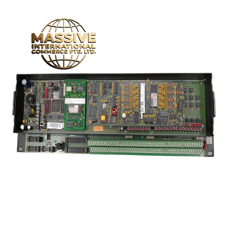
Description
GE D20C TERMINATION
Technical Specifications:
- CT Terminals: 5 pairs (10 terminals) for 3-phase + neutral + earth CT connections
- PT Terminals: 3 pairs (6 terminals) for 3-phase PT secondary connections
- Trip Output Terminals: 2 sets of form C contacts (trip + alarm), 4 terminals per set
- Binary I/O Terminals: 24-pin terminal block for 8811-IO-DC or similar modules
- Grounding Bar: Copper ground bus with 6 connection points
- Voltage Rating: 600V AC / 300V DC
- Current Rating: 5A per terminal (continuous), 10A peak (1 second)
- Terminal Type: Spring-clamp (push-in) with shrouded design
- Wire Size: 0.5mm² to 6mm² (AWG 20 to AWG 10)
- Operating Temperature: -25°C to +70°C
- Dimensions: Approximately 300mm x 100mm x 80mm (H x W x D)
- Weight: Approximately 1.2kg
- Standards: IEC 60947-7-1, UL 508, CE marked
Functional Features:
- Color-coded terminal groups: Red = CT, Blue = PT, Yellow = Trip, Green = Binary I/O, Black = Ground
- Shrouded terminal design prevents accidental contact with live terminals during wiring
- Clear circuit labeling strips for each terminal group
- Quick-disconnect wiring allows relay replacement without disturbing field wiring
- Ground bus bar with torque-marked connections (0.8Nm)
- DIN rail mounting compatible with D20C panel interior
- Front-accessible fuse holders for CT circuit protection (optional)
Application Scenarios:
- Final wiring point inside D20C protection panels
- CT/PT secondary circuit termination in substations
- Trip circuit connection to circuit breaker coils
- Factory pre-wiring station for panel assembly
- Retrofit wiring interface for existing panels
Performance Parameters:
- Contact Resistance: Less than 3mΩ per terminal
- Insulation Resistance: Greater than 100MΩ at 500V DC (between groups)
- Dielectric Strength: 2000V AC for 1 minute (CT to ground, PT to ground)
- Mechanical Life: 5,000 insertion/removal cycles (spring terminals)
- Vibration Resistance: IEC 60068-2-6 compliant (5g, 10-150Hz)
Material Composition:
- Housing: Flame-retardant polyamide 6.6 (PA66, UL94 V-0)
- Terminals: Copper alloy (C17200) with tin plating
- Ground Bar: Electrolytic tough pitch copper (ETP Cu) with tin plating
- Labeling: Laser-etched polycarbonate (chemical and UV resistant)
- Shrouds: Polycarbonate (transparent for visual inspection)
Structure Features:
- DIN rail mount (35mm) with snap-in clips
- Front-accessible for all wiring (no need to remove from panel)
- Modular design allows customization of terminal groups
- Cable entry from top or rear via PG16 glands
- Torque-indicating screws on ground bar connections
Working Principle: Field wiring from CTs, PTs, and trip coils enters the termination unit via the rear cable glands. Each wire is connected to the appropriate color-coded terminal group using the spring-clamp mechanism. The termination unit routes these signals to the D20C relays via the internal bus. The ground bar bonds all secondary circuits to the panel ground, ensuring safety and noise immunity. Installation Requirements:
- Mount on DIN rail inside the D20C panel at the rear
- Connect CT wires to the red terminal group (observe polarity: P1 to S1, P2 to S2)
- Connect PT wires to the blue terminal group (observe polarity)
- Connect trip coil wires to the yellow terminal group
- Connect binary I/O wires to the green terminal group
- Bond the ground bar to the panel ground bus using 6mm² green/yellow cable
- Torque all ground connections to 0.8Nm
Usage Notes:
- Always short CT secondary circuits when disconnecting wires (use the built-in shorting link)
- Verify all wire polarity before energizing (reverse polarity will cause relay misoperation)
- Use color-coded wire markers at both ends for easy troubleshooting
- Perform insulation resistance test (megger) between CT circuits and ground before energizing
- Label all wires according to the wiring diagram on the inside of the panel door