Description
GE IS210AEBIH3BED
- Technical Specifications:
- Series: GE Mark VI / Mark VIe
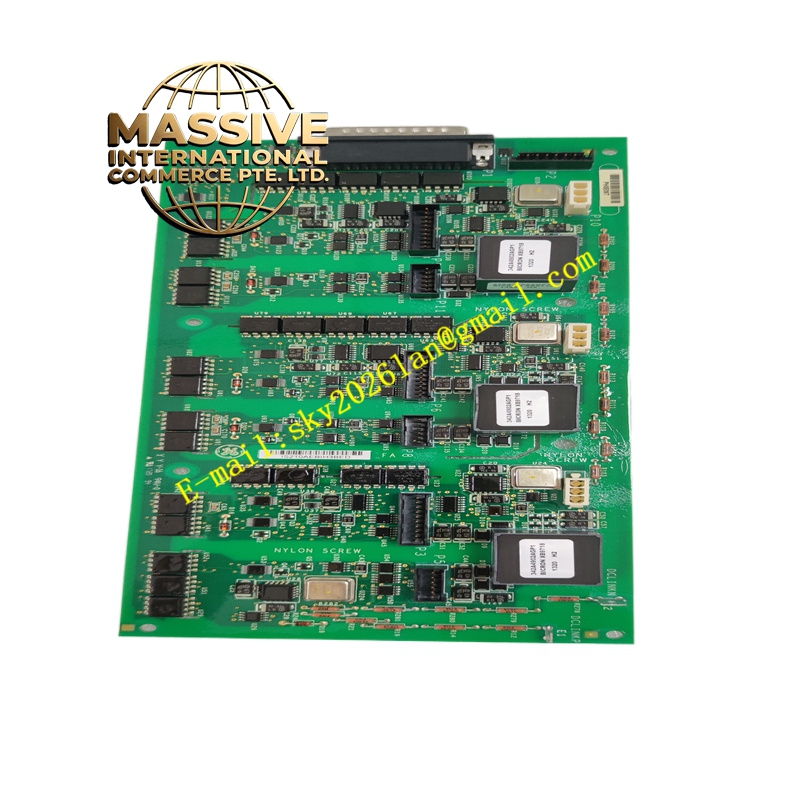
- Board Type: AE Bridge Interface Board
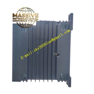
- Dimensions: Long, narrow rectangular board
- Weight: Approximately 0.34 kg (0.75 lb) before packaging
- Connectors:
- Right-angle connector along one short edge
- Seven vertical pin connectors
- Several three-position plug connectors
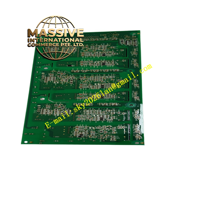
- Mounting: Drilled holes in corners and within the body for flexible installation options
- Functional Features:
- Provides AE bridging functions for communication between control and I/O subsystems
- Supports multiple connector types for versatile interfacing
- LED indicators for operational status and diagnostics
- Compact form factor suitable for tight-space installations
- Application Scenarios:
- Wind turbine control systems requiring robust bridging between modules
- Gas/steam turbine control racks where additional communication interfaces are needed
- Industrial automation requiring bridge boards in distributed control systems
- Performance Parameters:
- Designed for high reliability and long-term operation in harsh industrial environments
- Supports industrial temperature ranges and vibration conditions
- Material and Structural Characteristics:
- Industrial PCB material with high-quality components
- Robust connectors designed for secure and repeated connections
- Mounting holes and standoffs for stable mechanical attachment
- Working Principle:
- Acts as a bridge, routing data and control signals between the main controller and other modules or external networks. It ensures proper signal levels and timing compatibility across interfaces.
- Installation Requirements:
- Mount securely using the provided holes and hardware
- Align connectors carefully and ensure full engagement
- Follow power-down or hot-swap procedures per GE guidelines
- Verify correct orientation and slot assignment
- Usage Notes:
- Avoid bending connectors or applying excessive force during installation
- Use ESD protection when handling the board
- Periodically inspect for secure mounting and connector integrity
- Confirm compatibility with the specific Mark VI/VIe software version