Description
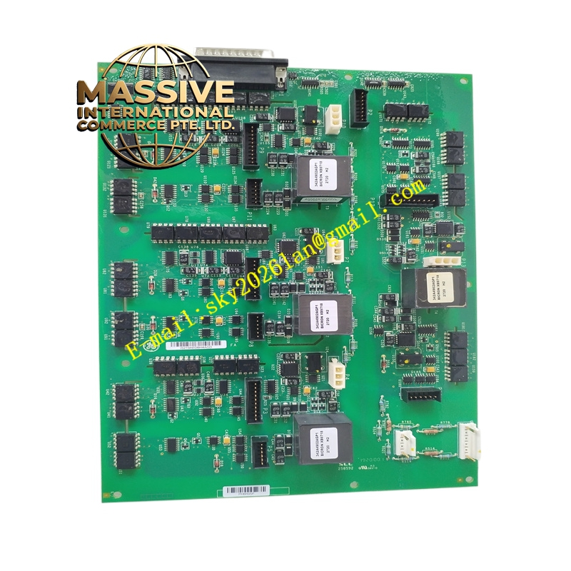
GE IS210AEDBH4AGD
- Technical Specifications:
- Series: GE Mark VI / Mark VIe
- Board Type: AE Data Bridge Interface (AE DB Bridge Interface)
- Function Revision: AGD
- Connectors: Multiple high-density connectors for data and power interfaces
- Environment: Designed for industrial temperature and humidity ranges typical of control cabinets
- Dimensions: Standard Mark VI/VIe board form factor
- Functional Features:
- Provides data bridging between control modules and external I/O networks
- Supports high-speed communication and data transfer within the control system
- Designed for compatibility with GE Speedtronic communication protocols
- LED indicators for board status and diagnostic information
- Application Scenarios:
- Gas/steam turbine control requiring additional data bridging or interface capabilities
- Wind turbine control systems where expanded data connectivity is needed
- Integration with external plant networks or third-party systems
- Performance Parameters:
- High reliability for continuous operation in critical control environments
- Low-latency data paths for real-time control communication
- Material and Structural Characteristics:
- Industrial-grade PCB with conformal coating options for environmental protection
- Robust connectors designed for multiple mating cycles
- Aluminum or steel front panel with secure mounting hardware
- Working Principle:
- Routes and bridges data between the main turbine controller and other subsystems or external networks. It may perform protocol conversion, signal buffering, or isolation depending on the specific application requirements.
- Installation Requirements:
- Install into a designated slot in the Mark VI/VIe rack
- Ensure proper alignment and seating of backplane connectors
- Route external cables and secure them to avoid strain on board connectors
- Follow GE installation procedures for power-down or hot-swap as applicable
- Usage Notes:
- Verify compatibility with the specific control system configuration and software version
- Use ESD protection when handling the board
- Periodically check connector condition and secure mounting
- Follow GE guidelines for diagnostic LED interpretation and maintenance