Description
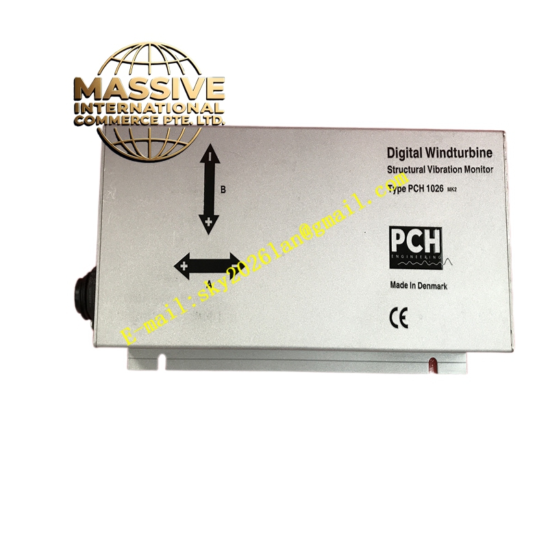
GE PCH1026
Technical Specifications:
- Model: PCH1026
- Manufacturer: GE (PCH Engineering)
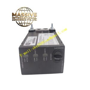
- Type: Digital structural vibration monitor
- Power Supply: 20–30 V DC
- Maximum Power Consumption: 7 W
- Input Channels: Up to 4 input channels
- Internal accelerometer: 3 axes (A, B, C)
- External accelerometers: Up to 4 (axes A and B)
- Dynamic Range: ±6 g
- Frequency Range: 0.1 Hz to 100 Hz
- Measurement Parameters: Acceleration, velocity, displacement
- Analysis: FFT analysis, tower frequency detection, real-time Zoom
- Communication Protocols: RS-485, RS-232, CANbus, CANopen, InterBUS, ProfiBUS, ProfiNet, ProfiSAFE, DeviceNET, EtherCat, Ethernet/TCP, USB
- Outputs: Up to 4 independent 4–20 mA analog outputs, up to 4 independent alarm relays, 1 system fault relay, 12 data channel outputs
- Optional: GL2010 certified Safety Shock Detection (SSD) card
- Configuration: Over 200 configuration options via PC software (RS232/USB service port)
- Dimensions: 254 mm x 130 mm x 66 mm
- Weight: Approximately 2 kg
- Working Temperature: -40 °C to +85 °C
- Mounting: Panel mount or DIN rail mount
Functional Features:
- Low-frequency vibration monitoring optimized for wind turbine and structural applications
- Built-in triaxial accelerometer for direct measurement without external sensors
- FFT analysis for drivetrain condition monitoring (turbine, main bearing, gearbox, generator)
- Tower frequency detection for structural health assessment
- Real-time Zoom FFT for detailed frequency analysis on up to 2 channels
- Configurable vibration threshold alarms with relay outputs
- Data logging for trend analysis and predictive maintenance
- Multiple communication protocols for integration with PLC and SCADA systems
- DNV-GL certified electronic Safety Shock Detection (SSD) system replacing traditional mechanical shock detection
- PC-based configuration software for easy setup and parameter changes
- Compatible with CHB 1100 series accelerometers for advanced nacelle monitoring
Application Scenarios:
- Wind turbine drivetrain monitoring: tower vibration, blade vibration, gearbox torsional vibration
- Industrial rotating equipment monitoring: pumps, fans, compressors, generators
- Structural vibration monitoring for buildings and bridges
- Seismic monitoring with multi-point sensor deployment
- Predictive maintenance programs for critical machinery
- Power generation plant condition monitoring
Performance Parameters:
- ±6 g dynamic range covering typical structural and machinery vibration levels
- 0.1 Hz to 100 Hz frequency range for low-frequency applications
- High-accuracy measurement of acceleration, velocity, and displacement
- Real-time analysis for fault detection and frequency identification
- Multiple alarm relays for immediate fault notification
- 4–20 mA analog outputs for integration with plant monitoring systems
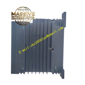
Material and Structural Characteristics:
- Industrial-grade metal enclosure (254 x 130 x 66 mm) for harsh environments
- Built-in triaxial accelerometer integrated into the monitor housing
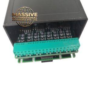
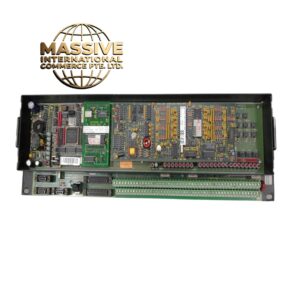
- PCB with high-resolution A/D converters and digital signal processor
- Front panel with status LEDs, communication ports, and service port (USB/RS-232)
- Terminal blocks for power, sensor inputs, analog outputs, and relay outputs
- Panel mount or DIN rail mount options for flexible installation
Working Principle: The PCH1026 acquires vibration signals from its internal triaxial accelerometer and up to four external accelerometers. The digital signal processor performs FFT analysis to convert time-domain signals into frequency spectra, identifying characteristic frequencies associated with mechanical faults (gearbox wear, bearing damage, tower resonance, blade imbalance). When vibration levels exceed configured thresholds, the monitor activates alarm relays and 4–20 mA analog outputs. The built-in SSD card detects sudden shock events (such as blade strikes or seismic events) and initiates safety shutdowns. Data is communicated to PLCs or SCADA systems via multiple industrial protocols for integration into plant-wide condition monitoring systems. Installation Requirements:
- Mount on a panel or DIN rail in the turbine nacelle, control cabinet, or monitoring room
- Connect 20–30 V DC power supply
- Install external accelerometers at critical measurement points (gearbox, generator, main bearing)
- Wire 4–20 mA analog outputs and alarm relays to the plant control system
- Connect communication cables (RS-485, Ethernet, or fieldbus) to the supervisory network
- Configure measurement channels, FFT parameters, alarm thresholds, and communication settings via PC software through the RS-232/USB service port
Usage Notes:
- Verify accelerometer sensitivity and range match the measurement requirements
- Configure alarm thresholds based on ISO 10816 or manufacturer guidelines for the monitored equipment
- Use shielded cables for accelerometer signals to minimize noise in low-frequency measurements
- Periodically verify calibration of internal and external accelerometers
- Update configuration when monitored equipment operating conditions change
- For wind turbine applications, configure the SSD card per GL2010 certification requirements
- Back up configuration settings after commissioning to facilitate replacement in case of failure