Description
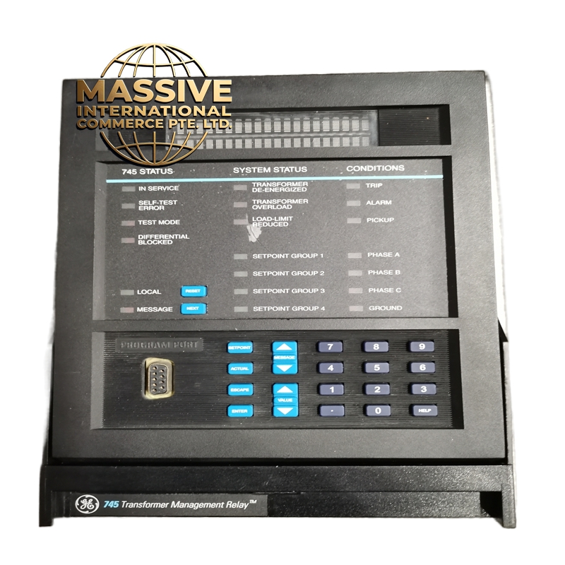
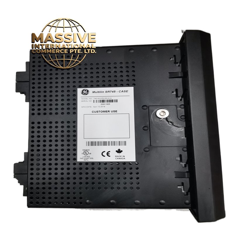
GE SR745-W2-P5-G5-HI-A
Technical Specifications
| Parameter | Specification |
|---|---|
| Product Family | SR 745 Transformer Management Relay |
| Input Voltage | 20-60V DC / 20-48V AC (48-62Hz) |
| Operating Temperature | -40°C to +60°C (with full load) |
| Storage Temperature | -40°C to +80°C |
| Logic Inputs | 16 logic inputs |
| Output Relays | 8 output relays |
| Communication Ports | RS232, RS485/RS422 |
| Optional Ethernet | 10Base-T (optional) |
| Mounting | 19-inch panel or DIN rail (TS 35/7.5) |
| Dimensions | 228.6 mm (H) x 177.8 mm (W) x 181 mm (D) |
| Weight | ~1.2 kg (2.65 lbs) |
| IP Rating | IP20 (indoor use) |
| Certifications | CE, IEEE C37.90, ANSI/IEEE Standards |
| Protocols | Modbus RTU, Modbus TCP (optional), DNP3 |
Functional Features
-
Percent Differential Protection: Harmonic-restrained differential protection with adaptive harmonic suppression
-
Overcurrent Protection: Phase and ground overcurrent with adaptive time-overcurrent elements
-
Overexcitation Protection: Volts-per-Hz (V/Hz) protection to prevent transformer core saturation
-
Frequency Protection: Underfrequency and overfrequency detection
-
Adaptive CT Ratio Mismatch Correction: Dynamic correction for CT ratio mismatches in real-time
-
Harmonic Monitoring: Individual and total harmonic distortion monitoring
-
FlexLogic Technology: Customizable logic configurations for unique protection strategies
-
High-Speed Sampling: 64 samples per cycle for rapid fault detection
-
Sequence of Events Recording: Time-stamped event recording for post-fault analysis
-
Enhanced Display: 40-character backlit LCD for clear status monitoring
Structural Characteristics
-
Industrial-grade components resistant to vibration and temperature fluctuations
-
Dust-resistant front panel with sealed enclosure
-
Compact design for space-constrained control panels
-
High-quality terminal blocks for secure wiring connections
-
LED status indicators for relay health and output states
-
Rugged 745 SR series chassis for mechanical protection
-
Conformal coating option for harsh environments
Working Principle The relay receives current signals from CTs on both sides of the transformer and voltage signals from VTs. It continuously calculates differential currents by comparing primary and secondary side currents, compensated for transformer turns ratio and vector group. The differential protection includes harmonic restraint to prevent false tripping during transformer inrush conditions. Overcurrent elements monitor for external faults, while overexcitation protection monitors the V/Hz ratio to prevent core saturation. The relay’s adaptive algorithms continuously adjust settings based on system conditions, providing optimal protection under varying operating scenarios.
Installation Requirements
-
Install in climate-controlled electrical room or substation control house
-
Connect CT and VT secondary circuits with proper fusing
-
Ensure correct polarity for all current and voltage connections
-
Configure transformer parameters (MVA, voltage ratio, vector group)
-
Set CT and VT ratios in relay configuration
-
Program protection settings based on transformer specifications
-
Verify proper grounding of instrument transformer secondaries
Application Scenarios
-
Power transformer protection in utility substations
-
Generator step-up transformer protection
-
Industrial plant main transformer protection
-
Distribution transformer monitoring
-
Auto-transformer protection schemes
-
Phase-shifting transformer protection
Usage Precautions
-
Ensure CT shorting blocks are in place before making connections
-
Verify correct CT polarity during commissioning
-
Program correct transformer turns ratio and vector group
-
Regular testing of differential protection recommended
-
Monitor harmonic restraint settings during commissioning
-
Maintain proper environmental conditions in relay room
-
Follow all electrical safety procedures during installation