Description
GE URRHH Technical Specifications:
- Input Voltage Range: Supports dual voltage ranges: Low Range (24 to 48 V DC nominal) and High Range (125 to 250 V DC/AC nominal).
- Power Output: Rated at 35 Watts.
- Internal Fuse: 4A / 250V internal fuse rating.
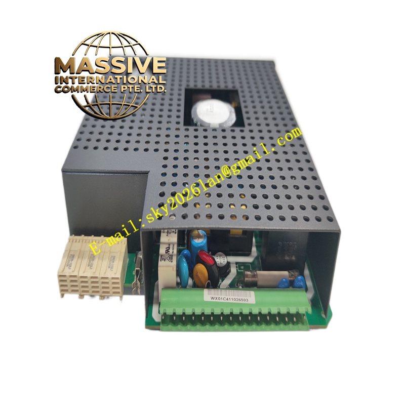
- Form Factor: Standard UR series plug-in module.
Functional Features:
- Dual Power Capability: Provides power to the relay system and also supplies power for dry contact input connections.
- Automated Health Monitoring: Integrates with the relay’s self-test elements to automatically assess power supply health.
- Fault Isolation: Automatically disables the power module in the event of critical hardware failure or detected faults.
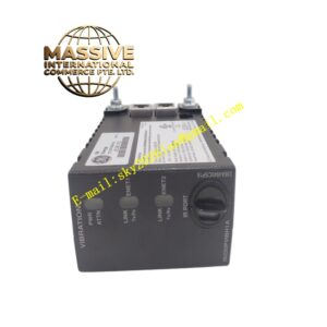
- Visual Diagnostics: Features dedicated front-panel LEDs (Up, Up/Down Cycle, Off) to indicate power status and operational state.
Application Scenarios:
- Powering UR series protective relays in substations and power generation facilities.
- Providing reliable DC power for industrial control panels.
- Upgrading older UR systems with second-generation power modules.
Performance Parameters:
- Efficiency: High-efficiency switching power supply design minimizing heat generation.
- Isolation: High dielectric isolation voltage (2000 V AC) ensuring safety and noise immunity.
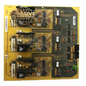
- Thermal Performance: Generates minimal heat despite 35W output, utilizing 27 electrolytic capacitors for stable filtering.
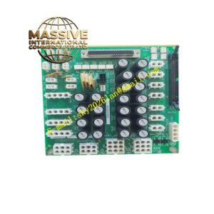
Material Composition & Structural Characteristics:
- Enclosure: Features a black matte finish chassis that enhances aesthetics and protects the underlying circuit board.
- Internal Components: Robust power electronics including switching transistors, transformers, and extensive electrolytic capacitor banks for ripple filtering.
- Indicators: Front-panel Light Emitting Diodes (LEDs) for immediate visual status feedback.
Working Principle: The URRHH accepts raw AC or DC input power and conditions it through an internal switching power supply circuit. It steps down and rectifies the voltage to provide clean, regulated DC power to the backplane. Continuous internal monitoring circuits check for overvoltage, undervoltage, and overcurrent conditions, triggering protective shutdowns and LED alerts if anomalies occur.
Installation Requirements:
- Compatibility: Verify the required input voltage range (Low or High) matches the facility’s power supply before installation.
- Mounting: Insert firmly into the designated power supply slot in the UR chassis and secure the retaining mechanism.
- Wiring: Connect input power using appropriately sized conductors and ensure tight terminal connections.
Usage Precautions:
- LED Monitoring: Regularly check the front-panel LEDs. A steady ‘Up’ LED indicates normal operation; flashing or off states indicate faults.
- Fuse Replacement: If the internal fuse blows, investigate the root cause of the short circuit before replacing the module.
- Redundancy: For critical applications, consider utilizing redundant power supply configurations if supported by the chassis.