Description
GE DS200NATOG3A
- Technical Specifications:
- Channels: 8 independent analog output channels
- Output Types: 4–20 mA (2-wire, loop-powered) or 0–10 VDC (4-wire)
- Output Range: User-programmable per channel (e.g., 4–20 mA = 0–100% valve stroke)
- Resolution: 12-bit D/A converter (4096 steps)
- Accuracy: ±0.1% of full scale (typical); ±0.2% after 5 years
- Update Rate: 10 ms per channel (all 8 channels updated simultaneously)
- Isolation: 500 channel-to-channel; 500 VDC channel-to-logic
- Load Capability: 4–20 mA output can drive up to 600 ohms loop resistance; 0–10 output can drive 10 kΩ minimum load
- Power Supply: +5 VDC from backplane; 4.0 W typical power consumption
- Diagnostics: Per-channel LED; loop fault detection (open circuit, short circuit); output saturation detection
- Functional Features:
- Independent Configuration: Each of the 8 channels can be set to a different output type (some 4–20 mA, some 0–10 ) without affecting other channels
- Fail-Safe Output: Configurable fail-to-zero (output goes to 0% on fault), fail-to-last (output holds last value), or fail-to-midscale (output goes to 50%)
- Loop Monitoring: Continuous monitoring of output loop for open circuit (wire break) and short circuit (output shorted to ground or supply)
- Ramp/Slew Rate: Programmable ramp rate from 0.1%/second to 100%/second for smooth valve movement and to prevent water hammer
- Initialization: On power-up, all outputs can be forced to a user-defined safe value (e.g., 0% for control valves, 100% for damper actuators)
- Application Scenarios:
- Steam Turbines: Control valve position command for throttle and governor valves; boiler feedwater regulating valve
- Gas Turbines: Fuel valve position; inlet guide vane position; exhaust temperature control damper
- Power Plants: Condenser cooling water valve; deaerator level control valve; chemical dosing pump speed
- Oil & Gas: Pipeline flow control valve; tank level control valve; flare damper position
- Water Treatment: Chemical feed pump speed; filter backwash valve; clarifier sludge valve
- Performance Parameters:
- Operating Temperature: 0°C to 60°C
- Storage Temperature: -40°C to 85°C
- Relative Humidity: 5% to 95% non-condensing
- MTBF: Greater than 170,000 hours
- EMC Compliance: IEC 61000-6-2, IEC 61000-6-4
- Material & Structure:
- Form Factor: Mark V/VI standard, approximately 170 mm × 100 mm × 25 mm
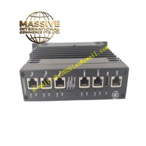
- Connectors: 32-pin backplane connector; 8 × 4-pin field terminal blocks (one per channel) on top
- PCB: 6-layer FR-4 with conformal coating
- Enclosure: Zinc-plated steel with EMI shielding
- Weight: Approximately 320 grams
- Front Panel: 8 green LEDs (one per channel, indicates output active); 1 amber fault LED; 1 green power LED
- Working Principle:
- The Mark V/VI CPU sends a 12-bit digital value to the board via the backplane bus. The value is latched by a register and presented to a 12-bit D/A converter. For 4–20 mA output, the D/A voltage drives a precision voltage-to-current converter (Howland current pump topology) that sources current into the field loop. The loop current is monitored by a sense resistor, and the feedback is used to maintain accuracy. For 0–10 VDC output, the D/A voltage is buffered by a precision op-amp with rail-to-rail output. The isolation barrier is provided by optical isolators between the backplane logic and the D/A converter, and by the current loop itself for 4–20 mA outputs (the loop is inherently isolated).
- Installation Requirements:
- Rack: Mark V or Mark VI I/O rack
- Wiring for 4–20 mA: Use shielded twisted-pair cable; connect the positive loop wire to the output terminal and the negative loop wire to the return terminal; the field device (valve positioner) completes the loop
- Wiring for 0–10 : Use shielded twisted-pair; connect the positive output to the field device input and the negative output to the field device common; the field device must have a high-impedance input (10 kΩ minimum)
- Loop Resistance: For 4–20 mA output, ensure total loop resistance (wire + field device) does not exceed 600 ohms at 24 VDC supply
- Grounding: Connect the shield to chassis ground at the control system end only
- Usage Notes:
- Do not leave a 4–20 mA output loop open; an open loop will cause the output to saturate at 20 mA and trigger a fault
- Ramp Rate: Always set a ramp rate for control valve applications; a sudden step change can cause water hammer in steam systems or mechanical shock in actuator systems
- Fail-Safe Selection: For safety-critical valves (e.g., turbine trip valve), always configure fail-to-zero so the valve closes on loss of signal
- Calibration: Use a precision mA meter or voltmeter to verify each channel at 0%, 25%, 50%, 75%, and 100% of output range; adjust zero and span via the Mark V/VI service software
- Channel Independence: Each channel has its own D/A converter and output stage; a failure on one channel does not affect the other seven channels