Description
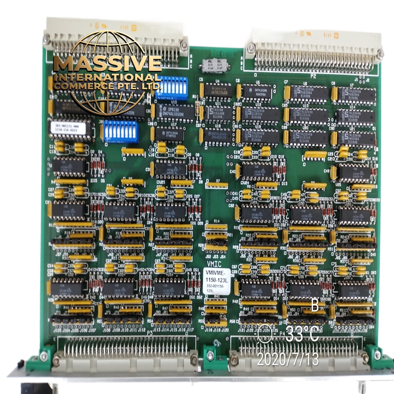
GE VMIVME-1150-123L
Technical Specifications
| Parameter | Specification |
|---|---|
| Function | 64-Channel Digital Input Board |
| Bus Interface | VME64x (32-bit/64-bit) |
| Input Channels | 64 optically coupled digital inputs |
| Input Voltage Range | 5V to 48V DC |
| Input Type | TTL level compatible |
| Isolation Voltage | 1,000V sustained, 7,500V pulsed |
| Response Time | Nanosecond level |
| Data Transfer | 8-bit or 16-bit, D8/D16 interface |
| Board Dimensions | Standard 6U VME form factor (233.35 mm x 160 mm) |
| Operating Temperature | 0°C to 55°C (32°F to 131°F) |
| Extended Temperature | -40°C to +85°C (industrial option) |
| Storage Temperature | -51°C to +100°C |
| Power Supply | From VME backplane (+5V, ±12V) |
| Power Consumption | < 15W typical |
Functional Features
-
High-Density Input: 64 digital input channels in a single VME slot
-
Optical Isolation: Complete electrical isolation between input channels and bus
-
Wide Input Range: Accepts 5V to 48V DC input signals
-
High Isolation Voltage: 1,000V sustained and 7,500V pulsed isolation
-
Flexible Data Transfer: Supports 8-bit or 16-bit data transfers
-
Filtered Input Options: Configurable input filtering for noise suppression
-
LED Status Indicators: Channel status LEDs for visual monitoring
-
VME64x Compatible: Full compatibility with VMEbus Rev 2.0 standard
Structural Characteristics
-
6U form factor with standard VME connector
-
High-quality optocouplers for each input channel
-
Multi-layer PCB with controlled impedance traces
-
Ruggedized front panel with I/O connectors
-
LED array for channel status indication
-
Conformal coating option for harsh environments
-
Metal shielding for EMI/RFI protection
Working Principle The VMIVME-1150-123L receives digital signals from external devices through 64 independent input channels. Each channel includes an optocoupler that provides complete galvanic isolation between the field wiring and the bus electronics. The input signal drives an LED within the optocoupler, and the resulting light is detected by a phototransistor on the side. This optical coupling eliminates ground loops and protects the system from high-voltage transients on the input lines. The board’s internal logic reads the state of all 64 inputs and makes the data available to the VME host processor via the bus interface.
Installation Requirements
-
Install in standard 6U chassis with proper card guides
-
Ensure proper card seating in VME backplane connectors
-
Connect field wiring to front panel terminal blocks or connectors
-
Configure base address and interrupt levels via DIP switches or software
-
Verify proper grounding of chassis and shield connections
-
Ensure adequate cooling airflow in enclosure
Application Scenarios
-
Industrial automation and process control
-
Aerospace and defense systems
-
Test and measurement equipment
-
Military radar and communication systems
-
Medical imaging equipment
-
Scientific instrumentation
-
Data acquisition systems
Usage Precautions
-
Verify input voltage levels are within 5-48V DC range
-
Do not exceed rated isolation voltage specifications
-
Ensure proper grounding to prevent ground loops
-
Use shielded cables in high-noise environments
-
Regular inspection of optocoupler performance recommended
-
Follow ESD handling procedures during installation
-
Maintain proper environmental conditions in VME enclosure