



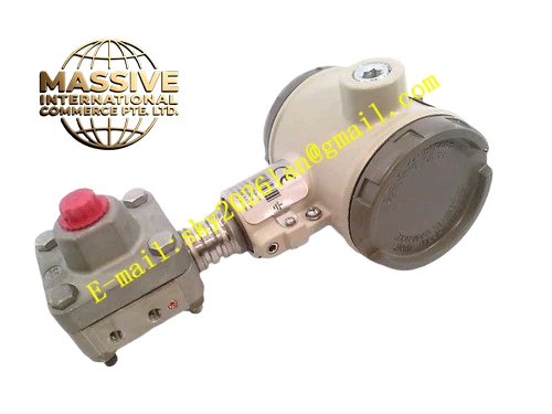
Description
Honeywell 8LS14C
Technical Specifications
- Contact rating: 10 A / 120 V AC, 6 A / 240 V AC
- Actuation type: Side-mount rotary lever with adjustable cam
- Mechanical life: 10 million operations
- Sealing rating: IP67 oil-tight sealed housing
- Operating temperature: -30 °C to +85 °C
- Mounting: Standard 2-hole panel mount
- Circuit configuration: 1 normally open, 1 normally closed snap-action contact
Functional Features Oil-tight die-cast housing withstands continuous exposure to plant washdown and oil mist. Adjustable rotary cam, supports field-configurable trip point for different travel stroke lengths. Snap-action contact mechanism, clean contact bounce-free switching even at slow actuator speeds. Positive opening contact design, forces contact open even under welded contact fault conditions for safety circuit compliance. Conduit entry for field cable wiring, threaded for watertight cable gland fit. Durable external lever pivot, corrosion resistant across years of outdoor operation.
Application Scenarios Over-travel protection for crane and hoist motion axes Conveyor end-of-trip position sensing Heavy machinery carriage limit position detection Gate and dam position feedback in water treatment plants Spare replacement for worn limit switches in harsh outdoor field installations
Performance Parameters
- Repeat accuracy: ±0.5° actuator rotation
- Contact bounce: <1 ms on actuation
- Insulation resistance: >1000 MΩ at 500 V DC
- Mechanical over-travel tolerance: ±30° past trip point without damage
- Vibration tolerance: 10–500 Hz, 5g acceleration without false tripping
Material Composition Zinc-plated die-cast aluminum housing Stainless steel rotary lever and pivot shaft Silver cadmium contact inserts NBR oil-resistant seal gaskets Brass cable conduit threads Thermoplastic internal contact carrier
Structural Features Rectangular sealed die-cast housing. Side-mount rotary lever extends from the housing face. Front two-hole mounting pattern matches industry standard limit switch footprint. Bottom 1/2 inch NPT conduit entry for cable wiring. Adjustable cam secured with set screw, marked with trip position scale.
Working Principle As moving mechanical equipment contacts the external rotary lever, the lever rotates around its pivot shaft. Internal cam profile presses against the snap-action contact plunger. When rotation crosses the preset cam angle, the snap-action mechanism flips, switching the normally open and normally closed contact states. Contact status is wired back to the motor control circuit, triggering stop or reverse action when travel reaches the trip point. Over-travel past the trip point does not damage internal contact components.
Installation Requirements Mount the switch using the standard 2-hole panel mount pattern, tighten mounting bolts to 4 N·m torque. Adjust the cam position so the lever trips at the required equipment travel limit. Run field cable through the bottom NPT conduit entry, use matching watertight cable gland. Wire NO/NC contacts to the motor safety stop circuit per control schematic. Manually actuate the lever during commissioning, confirm contact switches correctly at target trip point.
Usage Notes Do not apply impact force directly to the lever; shock loads above rated value bend the pivot shaft. Re-seal conduit entries after wiring to maintain IP67 sealing. Contact terminals must not exceed rated current; overloading causes contact welding. Lubricate the external pivot annually with light machine grease to prevent seized operation.







