



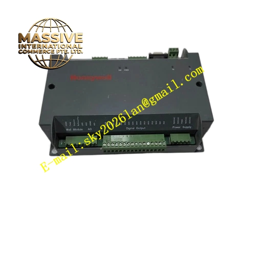
Description
Honeywell CP-DYNB-DI
Technical Specifications
- Channel Slot Quantity: 16 slots for digital input barrier modules
- Supported Signal: Dry contact, 24VDC discrete input
- Rated Terminal Voltage: 300V
- Wire Range: 22AWG to 14AWG copper conductor
- Working Temperature: -20°C to +70°C
- Storage Temperature: -40°C to +85°C
- Humidity: 5% to 95% RH non-condensing
- Intrinsic Safety Standard: IEC 60079, ATEX compliant
- Mounting: 35mm DIN rail or surface mounting
- Certification: ATEX, IECEx, UL, CE
Functional Features Each slot supports independent hot swap of digital input barrier. Separate field terminal and safe zone control terminal for each channel. Internal shared power bus supplies power for barrier modules. It supports barrier fault status output to DCS DI channel. Clear printed channel number marking on terminal cover. Mechanical anti-drop lock buckle for each barrier slot. It supports parallel power connection with adjacent DYN backplanes.
Application Scenarios Oil and gas pipeline hazardous area limit switch signal collection Refinery explosive zone valve feedback signal termination Chemical plant reactor interlock dry contact signal Offshore platform safety interlock discrete signal wiring Coal chemical plant hazardous area proximity switch monitoring Honeywell DCS intrinsic safety digital input cabinet spare
Performance Parameters
- Insulation Resistance: greater than 500 MΩ
- Terminal contact resistance: less than 10 milliohm
- Vibration test standard: 10-2000Hz, 1g continuous vibration
- Mean Time Between Failures: 1080000 hours
- Flame retardant grade: UL94 V-0
Material Composition FR4 flame retardant PCB substrate Nylon UL94 V-0 screw terminal block Tinned copper terminal pins Nickel plated copper power bus bar Steel DIN rail spring clip Transparent polycarbonate marking cover ABS plastic module locking buckle
Structural Features Flat rectangular backplane layout. Front side has two rows of terminals, field side and safe side separated. 16 barrier slots arranged on the middle area of backplane. Back side equipped with DIN rail elastic clip. Each slot has independent lock buckle. Channel number printed on transparent cover. Internal power bus runs horizontally through all slots.
Working Principle Discrete dry contact or 24VDC signal from field hazardous switch enters field side terminal. The signal passes through MTL digital input barrier module on the slot. The barrier limits energy to meet intrinsic safety requirement and transfers isolated discrete signal to safe side terminal. Safe side terminal connects to Honeywell DCS digital input module. Internal bus provides 24VDC power supply for each barrier.
Installation Requirements Fix backplane on DIN rail or cabinet surface with screws. Wire field hazardous side cable to field terminal and safe side cable to DCS DI module terminal. Insert matched MTL digital input barrier into each slot and lock buckle. Connect 24VDC power supply to backplane power terminal. Check signal continuity after wiring. Keep hazardous cable and safe cable separated in different wiring ducts.
Usage Notes Only MTL digital input barrier modules can be installed on this backplane. Do not install analog barrier modules on this DI backplane. All field wiring must follow intrinsic safety installation specification. Do not exceed rated voltage of terminals. Tighten terminal screws to avoid loose contact under vibration environment.







