



Description
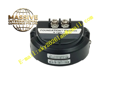
Honeywell HNS50049839-001
Technical Specifications
- Compatible Modules: Safety Manager CPU, power supply, SAI, SAO, SDI, SDO series I/O modules
- Bus Type: Redundant safety communication backplane bus, 24VDC power bus
- Rated Bus Voltage: 24VDC
- Maximum Total Rack Current: 30A
- Working Temperature: -20°C to +70°C
- Storage Temperature: -40°C to +85°C
- Relative Humidity: 5% to 90% RH non-condensing
- Isolation Rating: 1500VAC signal isolation
- Mounting: Fixed installation inside SIS rack chassis
- Certification: TÜV SIL2, UL, CE, FM
Functional Features It distributes stable 24VDC power supply to all rack slots. It provides redundant communication bus for high-speed safety data transmission between controller and I/O modules. It supports hot swap signal handshake when module is inserted or pulled out. It provides slot ID addressing circuit for each rack position. It supports redundant controller and redundant power supply bus sharing. It provides fault signal routing for module diagnostic alarm. It has dedicated ground bus bar for system safety grounding.
Application Scenarios Safety Manager FSC SIS main rack backplane Petrochemical ESD system rack motherboard replacement Offshore platform safety control rack spare part Refinery safety instrumented system rack maintenance Chemical plant reactor SIS cabinet backplane replacement
Performance Parameters
- Backplane Communication Speed: 1Mbps
- Insulation Resistance: Greater than 1000 MΩ
- Mean Time Between Failures: 990000 hours
- Bus Voltage Drop: Less than 0.2V at full rack load
- Contact Resistance of Gold Finger Connector: Less than 5 milliohm
Material Composition Thick FR4 flame retardant multilayer PCB Gold plated slot edge connectors Copper power bus layers Signal isolation resistors and capacitors Metal grounding bus bar Steel fixing screw and insulating spacer Nylon insulating support posts
Structural Features Large rectangular multilayer PCB backplane fixed inside rack chassis. Multiple slot gold finger connectors are arranged along the front edge for plug-in modules. Internal multilayer PCB separates power bus layer and signal bus layer. Ground bus runs through the whole board. Mounting holes and insulating spacers separate backplane from rack metal chassis. Each slot has dedicated addressing circuit trace.
Working Principle When modules are inserted into backplane slots, gold finger contacts connect module power pin, communication pin and signal pin to internal bus layers. The power bus transmits 24VDC power to every module. The redundant communication bus transmits safety control data, feedback signal and diagnostic message between CPU and I/O modules. The slot addressing circuit identifies module position and sends position information to controller. The ground bus provides unified reference potential for all rack modules.
Installation Requirements Power off the whole SIS rack before replacing backplane. Remove all plug-in modules from rack slots. Fix the backplane motherboard on rack chassis with insulating spacers and screws. Route system grounding cable to dedicated ground terminal. Reinstall all modules back into original slots according to slot number. Power on rack and download configuration, verify bus communication and module status. Torque all fixing screws to specified value.
Usage Notes Do not scratch gold plated contact surface on backplane slots. Static protection must be used during replacement. Do not short circuit power bus and signal bus. Confirm all modules are compatible with this backplane version. Keep backplane surface clean and free from conductive dust. Do not modify PCB trace or solder components on backplane.







