



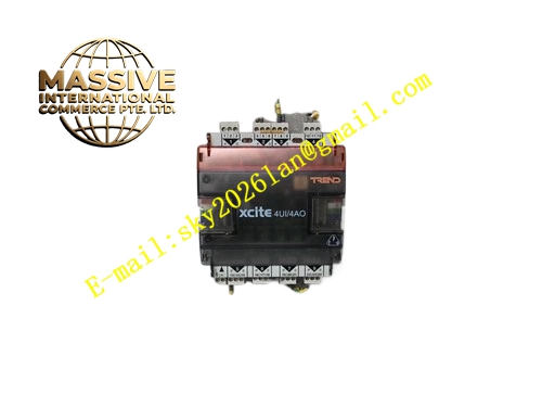
Description
Honeywell IQ3XCITE-IO-AUI-4AO
Technical Specifications
- Universal Input Channel: 4 channels
- Analog Output Channel: 4 channels
- Supported Input Signal: NTC10K, 0-10VDC, 0-20mA, resistance signal
- Output Signal Type: 0-10VDC modulating output, maximum 20mA source per channel
- Analog Resolution: 12 bit for input, 11 bit for output
- Communication Interface: XCITE dedicated I/O bus
- Working Ambient Temperature: 0°C to +60°C
- Storage Temperature: -40°C to +85°C
- Relative Humidity: 5% to 90% RH non-condensing
- Isolation Rating: 500VAC channel to logic isolation
- Mounting Method: TS35 DIN rail mounting
- Certification: UL60730, CE, RoHS
Functional Features 4 universal input channels support independent sensor type configuration. 4 analog output channels receive setpoint command from host controller and generate stable 0-10VDC modulating signal. It provides output loop overload and short circuit detection for each AO channel. It uploads input measurement value and output channel fault status to host controller. It has independent LED indicator for power, module fault, input and output channels. It adopts two-part removable terminal plug for easy wiring and replacement. It supports cascading on XCITE I/O bus with other XCITE I/O modules. It supports configurable safe state output value when communication fault occurs.
Application Scenarios Air handling unit cooling and heating water valve modulating control with temperature feedback Fan coil unit modulating valve control and room temperature monitoring Chiller bypass valve analog control and pressure signal collection Heat exchanger temperature regulating loop control Building ventilation damper modulating control with duct temperature feedback BMS mixed I/O point expansion for HVAC control cabinet
Performance Parameters
- Input Measurement Accuracy: ±0.3°C for NTC10K, ±0.5% full scale for voltage and current signal
- Output Regulation Accuracy: ±0.5% of full scale
- Output Response Time: Less than 0.4ms
- Insulation Resistance: Greater than 1000 MΩ
- Mean Time Between Failures: 900000 hours
- ESD Immunity: 8kV contact discharge
- Terminal Wiring Specification: 0.5mm² to 2.5mm² copper wire
Material Composition FR4 flame retardant PCB substrate ADC and DAC conversion chips Signal conditioning operational amplifier array TVS surge suppression diodes Current sampling precision resistors Nylon UL94 V-0 removable terminal block ABS flame retardant plastic housing Tri-color LED status indicators Steel DIN rail spring locking clip
Structural Features Compact DIN rail rectangular housing. Front panel integrates removable terminal plug and LED indicators for input and output channels. Rear side XCITE bus connector for interconnection with host controller or other I/O modules. Internal PCB separates analog input sampling zone, analog output driving zone and digital communication zone to reduce signal interference. Quick-release locking clip secures the module on DIN rail. Anti-misalignment notch prevents reverse bus insertion.
Working Principle Field sensor signal enters universal input channel and converts into digital value through ADC circuit. The digital measurement data is transmitted to IQ3XCITE host controller via XCITE I/O bus. Host controller sends modulating setpoint command back to the module according to control logic. DAC chip converts digital command into 0-10VDC analog driving signal to control actuator position. The sampling circuit continuously monitors output loop current. If overload or short circuit happens, the module triggers fault alarm and switches output to pre-configured safe state.
Installation Requirements Mount IQ3XCITE-IO-AUI-4AO on TS35 DIN rail inside dry control cabinet. Wire field sensor and actuator shielded cable to corresponding terminals. Connect XCITE I/O bus cable between module and host controller. Configure input sensor type, output range and communication fault safe state in IQ3 engineering software. Power on the bus and calibrate analog output range. Separate analog signal cable from high voltage power cable.
Usage Notes Each analog output channel load resistance must meet 0-10VDC load requirement. Do not connect inductive load directly to analog output terminals without surge protection. Shielded twisted pair cable is mandatory for all analog input and output wiring. Do not apply AC voltage to input







