



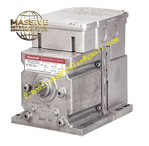
Description
Honeywell M8185D1006
Technical Specifications
- Power Supply: 24VAC, 50/60Hz
- Control Type: Two-position on-off control
- Rated Torque: 60 lb-in
- Adjustable Stroke Range: 90° to 160°
- Running Time: 60 seconds for full stroke
- Spring Return Action: Automatic return to safe position on power loss
- Working Ambient Temperature: -40°C to +67°C
- Storage Temperature: -40°C to +85°C
- Relative Humidity: 5% to 95% RH non-condensing
- Protection Grade: NEMA 3, IP54
- Mounting Method: Foot mounting bracket installation
- Certification: UL, C-UL, CE, FM
Functional Features Built-in heavy duty spring provides reliable automatic return to safe position during power failure. It supports field adjustable stroke angle to match different damper and valve travel requirement. It adopts dual ended slotted and tapped shaft for flexible linkage installation. It has integral junction box with quick connect wiring terminals. It supports adapter bracket to replace old generation Modutrol two-position motors. It maintains stable torque output within full voltage range. It has no auxiliary switch equipped on this model.
Application Scenarios Burner safety gas shutoff valve two-position control Fire smoke damper safety interlock actuator Boiler emergency shutdown air damper control Chemical plant safety isolation valve on-off drive HVAC fire smoke exhaust damper control Spring return safety actuator spare replacement
Performance Parameters
- Positioning Repeatability: ±1.5°
- Mean Time Between Failures: 790000 hours
- Mechanical Spring Cycle Life: 80000 full stroke cycles
- Power Consumption: 20VA during operation
- Operating Noise: Less than 58dB
Material Composition Die cast aluminum alloy housing AC servo motor Precision gear reduction assembly High strength return spring Position feedback potentiometer Signal and power wiring PCB circuit Quick connect plastic terminal block Steel crank arm and foot mounting bracket Silicone rubber sealing gasket
Structural Features Rectangular die cast aluminum housing with integrated wiring junction box. Dual ended output shaft for crank arm linkage installation. Internal spring chamber and gear chamber separated by structure partition. Removable front cover for stroke angle adjustment. Foot mounting base with fixed installation holes. Sealing gasket between housing and cover prevents dust and splash water ingress. Spring force direction is fixed to realize safe return action.
Working Principle When 24VAC power is applied, the motor drives gear set and output shaft to rotate against spring force to working position. The potentiometer tracks shaft rotation angle. When power supply is cut off, the stored elastic energy of return spring releases and drives shaft back to preset safe position. The gear set locks position when power stays on. The spring return action is passive and does not require external power supply.
Installation Requirements Install M8185D1006 on foot mounting bracket and connect crank arm linkage to valve or damper. Wire 24VAC power supply cable to junction box terminals. Adjust stroke angle after mechanical linkage installation to match equipment travel requirement. Power on actuator and test open action, then cut off power to verify spring return action. Keep actuator upright mounting to meet NEMA 3 protection rating.
Usage Notes Check spring return action regularly to ensure safe shutdown function. Do not exceed rated 60 lb-in torque load on output shaft. Mechanical linkage must move smoothly without jamming to avoid spring overload. Keep actuator away from continuous high temperature radiation. Do not manually force the shaft to rotate against spring direction.







