Description
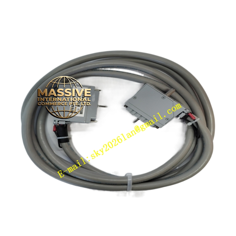
Triconex 400093-510
Technical Specifications:
- Type: External terminal input cable assembly
- Rated voltage: 24 V DC
- Length: Approximately 10 feet (3.05 m)
- Connector types: Triconex-specific plug/connector at each end, keyed to mating terminal boards
- Wire insulation: Industrial-grade PVC or equivalent, with shielding where applicable
- Operating temperature range: Typically 0 °C to 60 °C (per Tricon system environmental specifications; consult official manuals)
- Current rating: Compatible with low-voltage I/O signal levels; follow terminal board and module ratings
- Shielding: Options may include shielded constructions for noise immunity in electrically noisy environments
- Compliance: Designed to meet Triconex system EMC and environmental requirements
Functional Features:
- Pre-fabricated, tested cable assembly ensures consistent connection quality
- Keyed connectors prevent incorrect mating to terminal boards
- Supports secure, low-impedance signal paths for digital and analog I/O
- Facilitates hot-swap capability in TMR systems when used with appropriate terminal hardware
- Simplifies installation and maintenance by eliminating manual field wiring of individual conductors
Application Scenarios:
- Connecting Triconex I/O modules to external terminal panels in Tricon SIS cabinets
- Emergency shutdown (ESD) systems requiring reliable, noise-immune signal links
- Fire and gas (F&G) systems with distributed terminal panels
- High-integrity pressure protection systems (HIPPS) and burner management systems (BMS)
- Any Triconex installation where factory-made cable assemblies are preferred for reliability
Performance Parameters:
- Maintains signal integrity for 24 V DC digital and analog I/O
- Designed for minimal crosstalk and noise susceptibility
- Supports fast response times consistent with Triconex I/O module specifications
- Long service life with robust insulation and connector materials
Material and Structural Characteristics:
- Conductors: Copper strands for flexibility and current-carrying capacity
- Insulation/jacket: Industrial thermoplastic resistant to oils and common industrial chemicals
- Shielding (where applicable): Braided or foil shield with drain wire
- Connector housings: Thermoplastic or thermoset materials with metal shell where required for grounding
- Strain relief: Integrated at cable-to-connector transitions to prevent pull-out damage
Working Principle: The cable assembly electrically connects field-side terminal blocks to the Triconex I/O module backplane via the external termination assembly. Signals (e.g., 24 V digital inputs/outputs, analog 4–20 mA) pass through the cable with minimal loss and interference. Keyed connectors ensure correct orientation, reducing wiring errors. The assembly supports the Triple Modular Redundant (TMR) architecture by preserving signal integrity across redundant paths. Installation Requirements:
- Route the cable away from high-power lines to minimize electromagnetic interference
- Secure with cable ties to avoid strain on connectors
- Ensure connectors are fully seated and locked into mating terminal boards
- Verify that the cable part number matches the system configuration (voltage, length, shielding)
- Follow Triconex installation manuals for bend radius and conduit requirements
Usage Notes:
- Do not exceed rated voltage or current as specified by the Triconex system documentation
- Periodically inspect for insulation damage, connector corrosion, or wear
- Replace cables if any signs of damage or degraded performance are detected
- Use only Triconex-specified cable assemblies to maintain system certifications and SIL ratings