Description
Triconex 9566-810F Technical Specifications:
- Output Type: Electromechanical relay contacts (Form C/SPDT).
- Contact Rating: Typically 2A at 240VAC or 30VDC.
- Module Compatibility: Tricon relay output modules (e.g., 3623T, 3636R).
- Isolation: Full galvanic isolation between relay coil and contacts.
Functional Features:
- Universal Switching: Capable of switching both AC and DC loads without polarity concerns.
- High Isolation: Complete electrical separation protects the controller from field transients.
- Visual Indication: Mechanical flags or LEDs to indicate relay energized state.
- Test Points: Built-in test points for field loop verification.
Application Scenarios:
- Safety interlock relays for process equipment.
- Alarm annunciation and indicator lamp control.
- Motor starter and contactor coil control.
- Permissive signals to third-party control systems.
Performance Parameters:
- Mechanical Life: High-cycle rated relays (typically >10 million operations).
- Electrical Life: Rated for millions of operations at full load.
- Contact Resistance: Low and stable contact resistance over life.
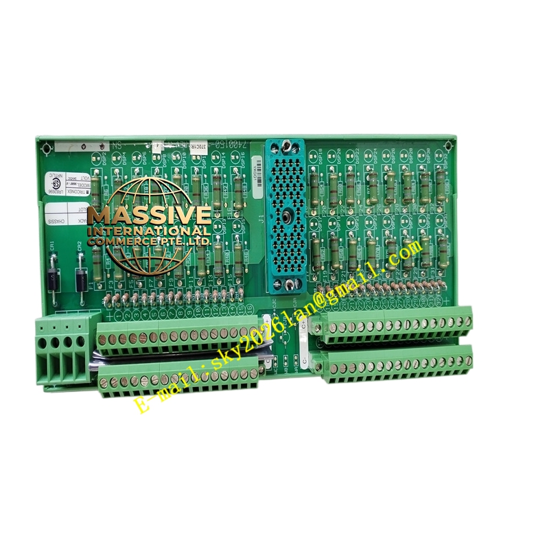
Material Composition & Structural Characteristics:
- Relays: Industrial-grade sealed relays with silver-alloy contacts.
- Housing: Flame-retardant thermoplastic with clear relay status windows.
- Terminals: Heavy-duty screw terminals for field and common connections.
- PCB: Robust board with heavy copper traces for relay coil current.
Working Principle: The Tricon relay module energizes the relay coil through the backplane. The magnetic field closes the relay contacts on the 9566-810F terminal board, completing the external field circuit. When the coil is de-energized, the contacts return to their normal state via a spring mechanism.
Installation Requirements:
- Common Wiring: Properly wire the common (COM) terminal for NO/NC configuration.
- Wire Size: Use wire rated for the load current and voltage.
- Snubbers: Install RC snubbers across AC loads to suppress arcing.
- Mounting: Secure the terminal board firmly to prevent vibration-induced loosening.
Usage Precautions:
- Inrush Current: Account for inrush current when switching capacitive or lamp loads.
- Contact Welding: Do not exceed contact ratings; welded contacts can compromise safety.
- Maintenance: Periodically verify relay operation and contact resistance.
- Replacement: Replace the entire terminal board if relay contacts are damaged.