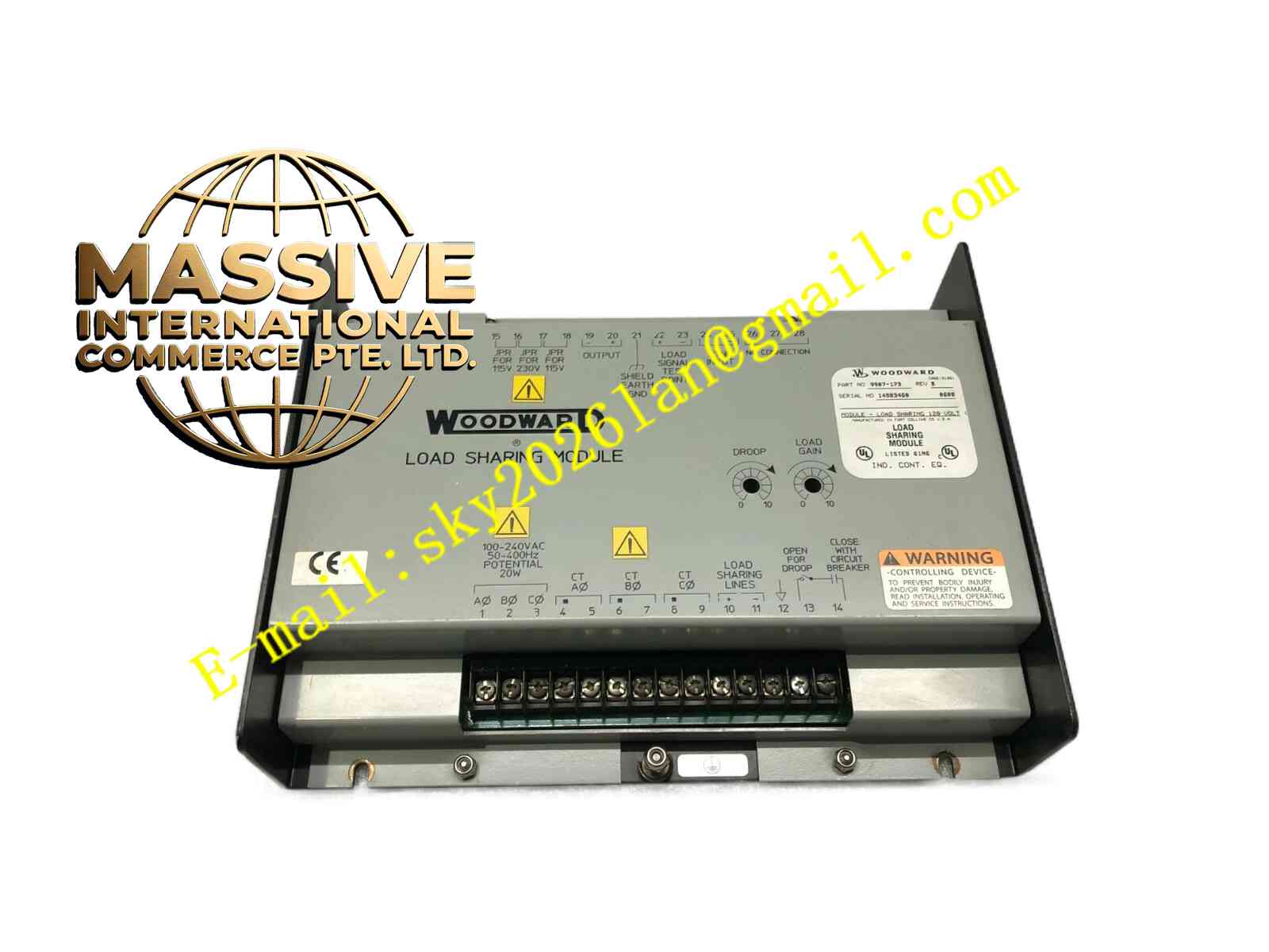
Description
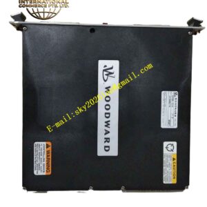
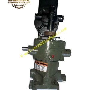
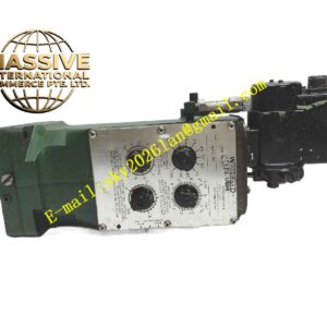
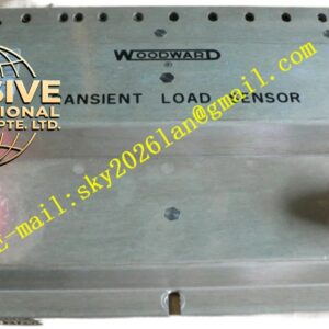
Woodward 9907-1197
Technical Specifications
- Function: Actuator driver and signal conditioning interface.
- Input Compatibility: Accepts standard analog control signals (4-20 mA, 0-10V) from electronic governors.
- Output Drive: High-current analog output capable of driving heavy-duty electro-hydraulic actuators.
- Feedback Input: Accepts LVDT or potentiometer feedback for closed-loop actuator positioning.
- Power Requirements: Regulated 24 VDC supply with internal over-current protection.
Functional Features
- Closed-Loop Positioning: Continuously compares command signals with actuator feedback to ensure exact valve positioning.
- Fail-Safe Operation: Automatically drives the actuator to a predefined safe position (e.g., fuel off) upon loss of power or signal.
- Signal Isolation: Provides galvanic isolation between the control system and field actuators to prevent ground loops.
- Diagnostic Outputs: Reports actuator faults, wiring breaks, and position errors to the main controller.
Application Scenarios
Essential in steam turbine control systems, large reciprocating engine fuel racks, and industrial gas turbine fuel valve actuation.
Performance Parameters
- Positioning Accuracy: Better than ±0.5% of full stroke.
- Response Time: Millisecond-level response to command signal changes.
- Drive Capacity: Sufficient current output to handle high-inertia actuators without stalling.
Material Composition
Constructed with high-reliability industrial electronics housed in a protective metal chassis. Terminals are gold-plated or nickel-plated to ensure long-term conductivity and corrosion resistance.
Structural Characteristics
- Mounting: Standard panel cutout or DIN rail mounting provisions.
- Indicators: Front-panel LEDs for power, command signal presence, and fault conditions.
- Wiring: Clearly labeled terminal blocks for straightforward field installation.
Working Principle
The module receives a low-level command signal from the governor and amplifies it to drive the actuator. Simultaneously, it reads the actuator’s position feedback. If the actual position deviates from the commanded position, the internal control loop adjusts the output current until the error is eliminated.
Installation Requirements
- Install in a clean, dry control panel with adequate ventilation.
- Use properly sized conductors for actuator power connections to minimize voltage drop.
- Ensure the feedback linkage is mechanically secure and free of backlash.
Usage Precautions
- Verify the fail-safe position matches the mechanical safety requirements of the prime mover.
- Do not bypass internal current-limiting protection circuits.
- Perform regular stroke tests to verify actuator response and feedback calibration.