Description
GE DS200TCPDG2B
- Technical Specifications:
- Channels: 2 independent PID temperature control channels
- Input Types: Thermocouple (J, K, T, E, N, S, R, B); RTD (Pt100, Pt1000, Cu50, Ni120)
- Input Resolution: 16-bit A/D converter
- Temperature Range: -200°C to +1800°C (depending on sensor type)
- Control Output: 4–20 mA (to control valve or damper actuator)
- Control Algorithm: PID with auto-tuning, adaptive gain, and bumpless transfer
- Sampling Rate: 10 samples per second per channel
- Accuracy: ±0.5°C (thermocouple); ±0.2°C (RTD)
- Isolation: 500 VDC channel-to-channel; 500 VDC channel-to-logic
- Power Consumption: 3.5 W typical
- Diagnostics: Per-channel LED; sensor fault detection (open, short, out-of-range); output fault detection
- Functional Features:
- Auto-Tuning: Built-in relay feedback auto-tuning (Zeigler-Nichols method) that automatically calculates optimal PID parameters; also supports manual PID entry
- Bumpless Transfer: When switching between manual and automatic modes, the output tracks the manual setpoint to avoid a sudden step change in the control valve
- Cascade Control: Channel B can be configured as a cascade slave to Channel A (e.g., Channel A controls main steam temperature, Channel B controls attemperator water flow as the inner loop)
- Alarm Limits: High-high, high, low, and low-low alarm setpoints per channel with configurable delay timers to prevent nuisance alarms
- Sensor Break Detection: Automatic detection of thermocouple wire break (open circuit) and RTD lead wire break; generates a diagnostic alarm
- Cold Junction Compensation: Built-in for thermocouple inputs with ±0.5°C accuracy
- Application Scenarios:
- Steam Turbines: Main steam temperature control (attemperator water valve); reheat steam temperature control; bearing journal temperature regulation (oil cooler valve)
- Gas Turbines: Exhaust gas temperature monitoring; compressor discharge temperature control; lube oil temperature regulation
- Generators: Stator winding temperature monitoring (RTD); rotor winding temperature monitoring (thermocouple); hydrogen cooler temperature control
- Industrial Process: Reactor temperature control; dryer temperature control; heat exchanger outlet temperature regulation
- HVAC: Chilled water temperature control; hot water boiler temperature regulation
- Performance Parameters:
- Operating Temperature: 0°C to 60°C
- Storage Temperature: -40°C to 85°C
- Relative Humidity: 5% to 95% non-condensing
- MTBF: Greater than 190,000 hours
- EMC Compliance: IEC 61000-6-2, IEC 61000-6-4
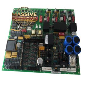
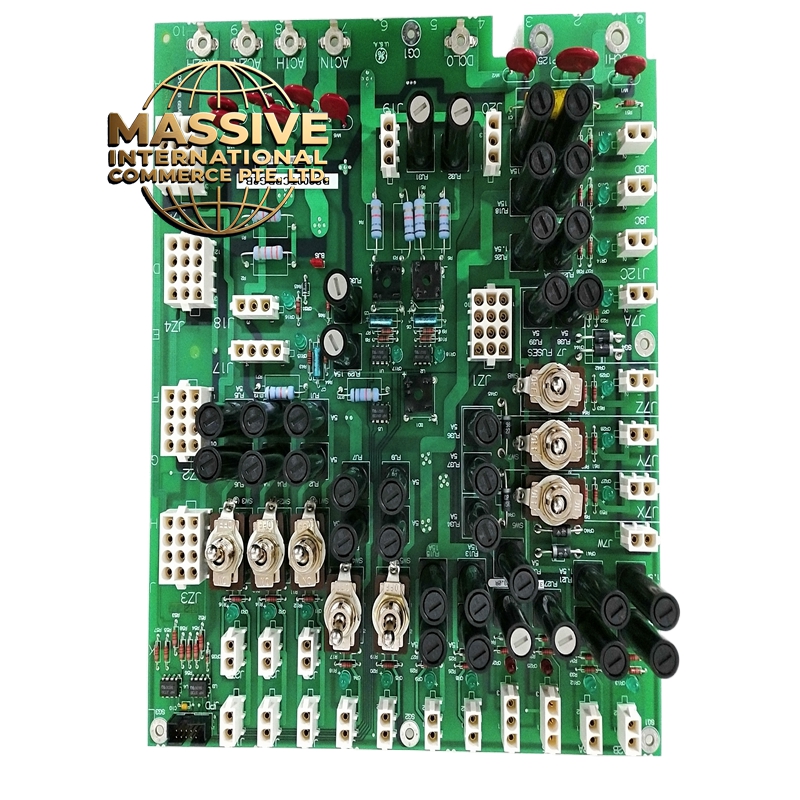
- Material & Structure:
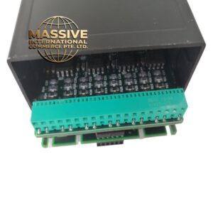
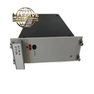
- Form Factor: Mark V/VI standard, approximately 170 mm × 100 mm × 25 mm
- Connectors: 28-pin backplane connector; 2 × 16-pin field terminal blocks (one per channel) on top
- PCB: 6-layer FR-4 with conformal coating and shielded analog sections
- Enclosure: Zinc-plated steel with EMI shielding can
- Weight: Approximately 340 grams
- Front Panel: 4 green LEDs per channel (power, run, alarm, fault); 1 amber system fault LED; 1 green power LED
- Working Principle:
- The temperature sensor signal is conditioned by a dedicated ASIC that performs cold junction compensation (for thermocouples), linearization, and 16-bit A/D conversion. The digital temperature value is compared to the setpoint, and the error is processed by a PID controller. The PID output is converted to a 4–20 mA signal by a 12-bit D/A converter and a voltage-to-current converter. The auto-tuning function injects a relay oscillation into the control loop, measures the resulting oscillation period and amplitude, and calculates the PID parameters using the Zeigler-Nichols formulas. The cascade control feature allows Channel B’s setpoint to be driven by Channel A’s output, creating a two-loop control system.
- Installation Requirements:
- Rack: Mark V or Mark VI I/O rack
- Thermocouple Wiring: Use thermocouple extension wire of the same type as the sensor; do not use copper wire; keep cable runs under 100 meters
- RTD Wiring: Use 3-wire or 4-wire configuration; the board supports both; 4-wire is recommended for highest accuracy
- Control Output: Connect the 4–20 mA output to the valve positioner or actuator; ensure loop resistance does not exceed 600 ohms
- Grounding: Connect shield to chassis ground at the control system end only
- Usage Notes:
- Auto-Tuning: Before running auto-tune, ensure the control valve is fully operational and the process is at steady state; auto-tuning will cause temporary oscillations
- Cascade Setup: When using cascade control, set Channel A as the master and Channel B as the slave; configure Channel B’s setpoint source to “Cascade from Channel A”
- Alarm Delay: Set alarm delay timers to at least 5 seconds to prevent nuisance alarms from sensor noise or transient temperature spikes
- Sensor Matching: Do not mix thermocouple types on the same channel; each channel must use a single thermocouple type
- Calibration: Calibrate each channel using a precision temperature simulator; verify accuracy at 0%, 25%, 50%, 75%, and 100% of the temperature range